
Solar Power Manager Series
Introduction
The DFRobot Solar Power Manager series are designed for IoT and renewable energy projects, providing safe and high-efficiency embedded solar power management modules for makers and application engineers. All modules in this series have MPPT (Maximum Power Point Tracking) to maximize solar energy conversion efficiency under various sunlight. A complete battery and power protection provides reliable power management for different types of solar projects.
Selection Guide
| Name | Solar Power Manager 1.0V | Solar Power Manager 5V V1.1 ★ | Solar Power Manager Micro V1.0 | Solar Power Manager For 12V Lead-Acid Battery V1.0 |
|---|---|---|---|---|
| SKU | DFR0535 | DFR0559 | DFR0579 | DFR0580 |
| Solar Power Management IC | LTC3652 | CN3165 | SPV1050 | CN3767 |
| Solar Input Voltage | 7V ~ 30V | 4.4V ~ 6V | 0.5V ~ 4V | 15V ~ 25V |
| Maximum Charge Current (Solar) | 2A (Solar/USB) | 900mA (Solar/USB) | 70mA (Solar)/100mA (USB) | 4A (Solar) |
| Topology | DC-DC Buck | Linear Regulator | DC-DC Boost | DC-DC Buck |
| Battery | 3.7V Lithium Battery | 3.7V Lithium Battery | 3.7V Lithium Battery | 12V Lead-Acid Battery |
| MPPT | 9V/12V/18V Optional | Fixed 5V | 75% Open Voltage | Fixed 18V |
| Battery Protections | Over Charge/Over Discharge/Over Current/Reverse Connection Protections | Over Charge/Over Discharge/Over Current/Reverse Connection Protections | Over Charge/Over Discharge/Reverse Connection Protections | Over Charge/Over Discharge/Reverse Connection Protections |
| Output Protections | Short Circuit/Over Current/Over Heat Protections | Short Circuit/Over Current Protections | Short Circuit/Over Current Protections | Short Circuit/Over Current/Over Heat Protections |
| USB Charge IN | Yes | Yes | Yes | No |
| USB OUT | 5V 1.5A | 5V 1A | No | 5V 2.5A X2 |
| Regulated OUT | Three Regulated Outputs 3.3V 1A;5V 1.5V;9V/12V 0.5A |
One Regulated Output 5V 1A |
One Regulated Output 3.3V 90mA |
Two Outputs 5V 5A; 12V 8A |
| Dimension | 78.0mm×68.0mm | 33.0mm×63.0mm | 30.0mm×30.0mm | 68.0mm×68.0mm |
| Features | A complete multifunction solar power management module. Applications: Small Solar Street Lamp, Solar Powered Robots For 9V/12V/18V Solar Panels within 20W |
A small and easy-to-use 5V solar power management module. Applications: Solar Power Bank, Solar Environment Monitors For 5V Solar Panels within 10W |
A micro power solar power management module for low-power sensors and controllers. Applications: Wireless Sensor Network, BLE iBecon For 1V/2V/3V Solar Panels within 0.5W |
Medium power solar management module for 12V lead-acid batteries. Applications: Street lighting, intelligent agriculture, environmental monitoring station For 18V Solar Panels within 100W |
Introduction
Solar Power Manager 5V is a small power and high-efficiency solar power management module designed for 5V solar panel. It features as MPPT (Maximum Power Point Tracking) function, maximizing the efficiency of the solar panel. The module can provide up to 900mA charging current to 3.7V Li battery with USB charger or solar panel. The ON/OFF controllable DC-DC converters with 5V 1A output satisfies the needs of various solar power projects and low-power applications. The module also employs various protection functions for battery, solar panel and output, which greatly improves the stability and safety of your solar projects.
Version History
- V1.0: It is highly recommended to use a 3.7V lipo battery with protection circuits to improve battery safety.
- V1.1(Newest): Battery (BAT IN) overcurrent and overdischarge protection is added to improve battery safety. It can be use for 3.7 lipo battery no matter it is packed with protection circuits or not.
Features
- Constant Voltage MPPT Algorithm, Maximizing Solar Panel Efficiency
- Designed for 5V Solar Panel
- Double Charging Mode: Solar/USB Charger (900mA Max Charge Current)
- 5V ON/OFF Controllable Regulated Power Supply for Low-Power Applications
- Various Protection Functions
- USB Connector with ESD Shell
Specifications
- Solar Power Management IC: CN3165
- Solar Input Voltage (SOLAR IN): 4.5V~6V
- Battery Input (BAT IN): 3.7V Li-Polymer/Li-ion Battery
- Charge Current (USB/SOLAR IN): 900mA Max Trickle Charging, Constant Current, Constant Voltage Three Phases Charging
- Charge Cutoff Voltage (USB/SOLAR IN): 4.2V±1%
- USB IN Voltage: 5V
- Regulated Power Supply: 5V 1A
- Regulated Power Supply Efficiency (3.7V Battery IN)
- 5V/USB OUT: 89%@10%Load, 86%@50%Load, 83%@90%Load
- USB/Solar Charge Efficiency: 73%@3.7V 900mA BAT IN
- Maximum Quiescent Current: <1 mA
- Protection Functions
- BAT IN: Over Charge Voltage (4.3V)/Over Discharge Voltage (2.4V) /Over Current (3A) /Reverse Connection Protection
- 5V/USB OUT: Short Circuit/Over Current/Over Heat Protection
- SOLAR IN: Reverse Connection Protection
- Operation Temperature: -40℃~85℃
- Dimension: 33×63 mm / 1.30×2.48 in
- Weight: 12 g
Applications
- Smart Solar Powered Environment Monitor System
- Solar Powered Robots
- Small Solar Street Lamp
- Solar Power Bank
Board Overview
.png)
Quick Start
Build a solar powered system
Connect the Li battery to BAT IN.
Connect the solar panel to SOLAR IN.
Connect USB OUT of the module to Arduino with USB cable.
Connect all the VCC and GND pins of the peripherals to the regulated power supply headers 5V and GND.
Insert the jumper on the ON of the blue header.
Attention
- Each time the BAT IN terminal battery is replaced, the module USB OUT/5V pin header (red) does not output immediately due to the function of the lithium battery protection. The output can be restored by pressing the BOOT button or charging the battery in one of the USB/SOLAR IN ports.
- If a 5W (or above) solar panel or USB charger is used, the CN3165 may run in full load, trying to charge the battery at maximum 900mA. In order to improve the cooling of the IC, it is highly recommended to attach the thermal conductive silicone pad and Aluminum cooling fin (included in the kit) to the bottom of the module where the label "Cooling Fin" is located.
.png)
Detailed Description
Maximum Power Point Tracking, MPPT
The MPPT (Maximum Power Point Tracking) can ensure the solar panel output power maintains at its maximum under different loads and sunlight, maximizing the conversion efficiency. We can identify the short circuit current ISC and the open circuit voltage VOC from the cross points of the I/V curve (green) with x and y axis respectively. The ISC and VOC grow larger with the illumination increasing. With the output voltage VPANEL growing, the output current IPANEL gradually decreases and then jumps down after crosses a special point VMP, the maximum power voltage. By multiplying the voltage and current, which obviously results in power, and take the output voltage as the x axis, we obtain the P/V curve (blue). The output power PPANEL reaches its peak when the output voltage is at VMP. Although the maximum power increases with illumination, the VMP changes little. Therefore, we may approximately take the VMP as a constant for a specific solar panel under different illumination.
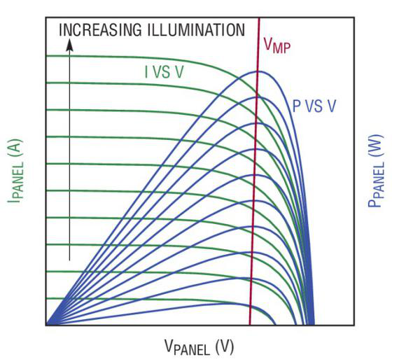
"IV/PV characteristic curve of a typical solar panel (picture from Linear Technology)") Inspired by the observation above, the CN3165 solar power management IC (employed by this module) maximizes the output power by keeping the output voltage at the vicinity of VMP, which is also called constant voltage MPPT algorithm. Benefited from this feature, the module has a better conversion efficiency compared to common linear battery charger.
Charging Cycle
The module safely and quickly charges lithium battery through three phases: trickle charge, constant current charge, constant voltage charge.
- Trickle charge: Since the internal resistance of the lithium battery becomes high when the voltage is low, it is not a good manner to charge with large current at the beginning. Otherwise, the battery temperature rises and the battery life is lowered. When the battery voltage is lower than the trickle charge threshold voltage of 3V, the module enters the trickle charge phase, charging the battery at 10% of the maximum charge current up to 90mA, until the battery voltage is higher than 3V.
- Constant current charge: When the battery voltage is higher than 3V, the module enters the constant current charging phase, and the battery is charged with a constant current up to 900mA. During the phases of trickle and constant current charge, the CHG red LED turns ON and the DONE green LED turns OFF.
- Constant voltage charge: When the battery voltage is closing to the charge cut-off voltage of 4.2V, the module enters the constant voltage charge phase. The module continues to charge the battery with a constant voltage, and the charging current gradually decreases. When the charging current drops to 10% of the maximum charging current of 90mA, the charging ends. The CHG red LED turns OFF and the DONE green LED turns ON.
- Automatic recharge: If the battery is fully charged (DONE ON), the module input source (SOLAR IN) not powered off and the battery voltage decreases due to self-discharge or load, when the battery voltage drops below 4.05V, a new charging cycle will automatically begin.
.png)
Solar Panel Selection
The module is designed for 5V (nominal/maximum power voltage) solar panel. Any kinds of panel (monocrystal, polycrystal, thin flim) can be employed as long as the open circuit voltage is less than 6.5V. Taking the size, weight, price of the panel and the 900mA maximum charge current of the module all these factors into consideration, it is recommended to connect a solar panel with no more than 10W to the SOLAR IN terminal.
NOTE: The input voltage of SOLAR IN SHOULD NOT exceed 6.5V, or the module may be permanently damaged.
Battery Selection
The battery input BAT IN provides two connectors JST PH2.0 and KF396 3.96mm 2P terminal, which directly connect each other internally. Usually, connect one 3.7V Li-polymer/Li-ion battery (4.2V when fully charged) to one of the connectors. The maximum charge current can be up to 900mA for both USB IN or SOLAR IN. Safety issue may arise if the charging current exceeds the nominal charge current of the battery, which is often determined by the capacity and charge rate of a battery. The maximum allowable charge current of a battery can be calculated with the equation: Maximum charge current(mA) = Capacity(mAH) * Charge rate(C). Use this equation to check whether the battery is suitable. For commonly used 1C (charge rate) Li battery, the capacity should be at less 900mAh. For higher charge rate battery, smaller capacity can be used. Some Li batteries are packed with battery protection circuit to automatically limit the charge/discharge current. For such batteries, users are free of worrying about the charge current issue stated above.
USB Charge Requirement
The USB IN is only used for battery charging. It is recommended to use at less a 5V 1A AC adapter for battery charging.
USB/SOLAR IN Automatic Switching
Both the USB IN and SOLAR IN are capable of deliver 900mA max charge current. To prevent charge conflict caused by using both inputs, the USB charge has a higher priority. When the USB IN is powered on by AC adapter, the SOLAR IN will be automatically cut off. When the USB IN is powered down, the SOLAR IN resumes charging.
Regulated Power Supply
The module provides a ON/OFF controllable 5V 1A regulated output. The 5V outputs of the header and USB OUT share the same output voltage and maximum current, however, USB OUT CAN NOT be shutdown.
Most of the power banks available on the market has the automatic shutdown function to reduce the quiescent power under light loads. However, the automatic shutdown threshold is usually higher than many low power controllers, some even higher than the classical Arduino UNO (around 50mA). Such power banks will automatically shut itself down when the output current continues lower than some preset threshold after several seconds, which fails to apply to low power applications. The USB OUT employs the low quiescent power DC-DC boost converter and always remains ON to provide continuous power to low power controller.
Except from USB OUT, the header 5V output can be turned ON/OFF by all 3.3V and 5V controllers (such as Arduino, FireBeetle or Raspberry Pi etc.). Pull out the jumper on the blue header, the output will be shutdown (LED indicator ON turns dark). Connect any IO and GND pin of the controller to the EN and GND pin of the blue header. When the IO pin is driven HIGH, the regulated output turns on. When driven LOW, the output turns OFF. This function is extremely useful in low power application. For example, connect all VCC and GND pins of the peripherals (sensors or other modules) to the 5V and GND pins. Turn on the regulated output and read all the data from the sensors. Turn off the output and put the controller into sleep mode for 1s (for example) until next wake up. By cycling the system into such discontinuous (or pulse) operation pattern, the average power consumption can be greatly reduced. Average power consumption and data acquisition interval are the trade off under such situation.
Attention
- Turn off 5V header output will not turn off USB OUT 5V output, which CAN NOT be shutdown. The total output power of USB OUT and 5V header should not exceed 5V*1.5A=7.5W.
- Pay attention to the differences of the GND on the black header and blue header, though they share the same names. When the 5V output turns ON, the "GND" on the black header is connected to the system ground GND. When the 5V output turns OFF, they are disconnected. The GND on the blue header is the system ground GND.
LED Indicators
There are three types of LED indicators indicating the operation status of different parts of the module:
- Reverse connection LED indicators: when the battery or solar panel are reverse connected at the BAT IN or SOLAR IN, the corresponding orange LEDs REV BAT or REV SOLAR turns ON, informing the user a reverse connection error.

- Charge LED indicators: when using the USB IN or SOLAR IN to charge the battery, the CHG LED (red) turns ON. If the battery is fully charged, the CHG LED turns OFF and the DONE LED (green) turns ON. If the battery is not connected, both CHG and DONE turn ON.

- Regulated output LED indicator: The ON LED(green) indicates the ON/OFF status of the 5V regulated output. The LED turns ON when the output turns ON and vice versa. Again, the USB OUT can not be shut down and has no LED indicator. Once one of the USB IN, BAT IN or SOLAR IN are available, the USB OUT outputs a 5V.

Cooling Fin installation
If an USB AC adapter or a 10W (or above) solar panel is used, the solar power management IC CN3165 may run into full-load. The chip has over-temperature protection function, which will automatically limit the charge current, trying to protect the chip. To improve cooling and maximize charge current, which results in longer life-span and better performance, it is highly recommended to stick the Aluminum cooling fin with the blue thermal conductive silica pad to the bottom of the module, where the label “Cooling Fin” is located.

Protection Functions
- Reverse connection protection: On the BAT IN and SOLAR IN, the reverse connection protection circuit prevents the reverse voltage from damaging the module and the corresponding LED will light up to inform the user.
- Regulated output protection: When the output are accidentally shorted or output current beyond 1A (over load), the output will be complete shutdown to protect the output regulator.
- Li-battery protection: The module employs a dedicated Li-battery protection chip to improve the life-span and safety of the battery. When the battery voltage exceeds 4.3V, the chip shut down the charge path to prevent it from further being charged (but still allow discharging). When the battery voltage drops below 2.4V, the output of the battery is shut down to prevent it from further being discharged. It is likely to cause permanent damage to the “fragile” battery, if it is extremely over discharge or charge. Most of the battery charger can prevent over charge by internally setting the cut off charge voltage to 4.2V for Li battery, but the over discharge situation can only be guaranteed by the battery protection IC packed inside the battery or on the power management module like this one. When the discharge current of the battery exceeds 3A, the discharge path of the battery is shut down.
Application Examples
Use the USB to charge battery
Ultilize the USB charge function, the user can build a USB/solar power bank for outdoor sport application. Charge the battery with solar panel by daytime and USB at night with cell phone charger (if it is available). User can also charge small charge current, low power devices, such as smart band or Bluetooth headset with the USB OUT.
.png)
Build a low power environment monitor station
This application example use the BME280 environmental sensor to record temperature, humidity and atmospheric pressure, VEML7700 ambient light sensor to record the the ambient illumination, and DS1307 RTC module to record time. Use the analog input A1 to monitor the battery voltage (equivalently the battery capacity). To achieve lower power consumption, use one Arduino digital IO pin to turn ON the power supply, read all the data from the sensors and turn them OFF. Cycle this pattern for a proper interval T to reduce the average power consumption. This can completely get rid of the quiescent power of the peripheral modules. Although single peripheral may consume little power, it can be considerable large for a number of them. This module provides users with effective methods to drive the peripheral modules into discontinuous (pulse) mode to achieve low power operation.
.png)
FAQ
For any questions, advice or cool ideas to share, please visit the DFRobot Forum.
More Documents
DSC-CN3165 Datasheet (Chinese)
 Get Solar Power Manager 5V from DFRobot Store or DFRobot Distributor.