GPIO Board Wiki (Older Hardware Revision)
This page documents the legacy GPIO Board (older hardware revision). It is retained for reference only.
Introduction
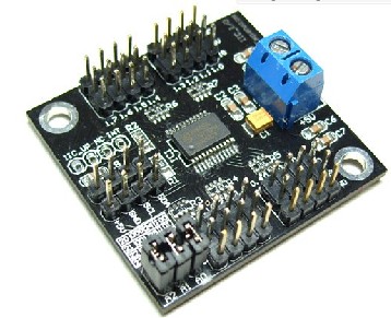
When Arduino is used for robots or interactive media, digital IO port is always found not enough? I2C now turn I / O modules to help you solve the problem, Arduino only two data lines (SCL-Analog PIN5, SDA-Analog PIN4) and I2C can transfer I/O module communication, to convert the 16 digital IO ports, read-write. 8 simultaneous parallel modules, each module can be set to address.
Specification
- Module power supply: +5 V
- 16 Digital IO port comes with internal pull-up
- Can be set to eight addresses (address range of 0x20 ~ 0x27)
- 8 modules simultaneously in parallel (I2C bus need to pull together)
- Module Size: 42x40mm
Sample Code
/******************************************************************************
Test Program for the 12C PCA9555 Board part number DFR0013 I2C TO GPIO module from dfrobot.com
16 outputs that I used to drive this relay board made in Bulgaria
http://www.denkovi.com/product/21/16-relay-board-for-your-pic-avr-project-12v.html
it's a great little expansion board that can be used to drive LEDs or anything you want.
made by [email protected]
January 07th 2011
My biggest problem was figuring out the I2C address of the PCA9555.
If there are no jumpers the address is 1 0 0 '1 1 1'
Jumpers make the address 1 0 0 '0 0 0'. This is opposite of what I expected.
******************************************************************************/

#include <Wire.h>

//  with no jumpers the full address is   1 0 0 1 1 1    1 0 0 A2 A1 A0  0x27 is the default address for the DFR0013 board with no jumpers.
#define PCA9555 0x27 // 0x27 is default address for the DFR0013 board with no jumpers.
                     // 0x20 is address for the DFR0013 board with all jumpers.
// COMMAND BYTE TO REGISTER RELATIONSHIP FROM PCA9555 DATA SHEET
// At reset, the device's ports are inputs with a high value resistor pull-ups to VDD
// If relays turning on during power up are a problem. Add a pull down resistor to each relay transistor base.

#define IN_P0 0x00 // Read Input port0
#define IN_P1 0x01 // Read Input port1
#define OUT_P0 0x02 // Write Output port0
#define OUT_P1 0x03 // Write Output port1
#define INV_P0 0x04 // Input Port Polarity Inversion port0 if B11111111 is written input polarity is inverted
#define INV_P1 0x05 // Input Port Polarity Inversion port1 if B11111111 is written input polarity is inverted
#define CONFIG_P0 0x06 // Configuration port0 configures the direction of the I/O pins 0 is output 1 is input
#define CONFIG_P1 0x07 // Configuration port1 configures the direction of the I/O pins 0 is output 1 is input

#define PAUSE 200

void setup()
{
  Wire.begin(PCA9555); // join i2c bus (address optional for master) tried to get working
  write_io (CONFIG_P0, B00000000); //defines all pins on Port0 are outputs
  write_io (CONFIG_P1, B00000000); //defines all pins on Port1 are outputs
  write_io (OUT_P0, B00000000); //clears all relays
  write_io (OUT_P1, B00000000); //clears all relays
  delay (PAUSE);
}


void loop()
{
  write_io (OUT_P0, B00000001);
  delay (PAUSE);
  write_io (OUT_P0, B00000010);
  delay (PAUSE);
  write_io (OUT_P0, B00000100);
  delay (PAUSE);
  write_io (OUT_P0, B00001000);
  delay (PAUSE);
  write_io (OUT_P0, B00010000);
  delay (PAUSE);
  write_io (OUT_P0, B00100000);
  delay (PAUSE);
  write_io (OUT_P0, B01000000);
  delay (PAUSE);
  write_io (OUT_P0, B10000000);
  delay (PAUSE);
  write_io (OUT_P0, B00000000);


  write_io (OUT_P1, B00000001);
  delay (PAUSE);
  write_io (OUT_P1, B00000010);
  delay (PAUSE);
  write_io (OUT_P1, B00000100);
  delay (PAUSE);
  write_io (OUT_P1, B00001000);
  delay (PAUSE);
  write_io (OUT_P1, B00010000);
  delay (PAUSE);
  write_io (OUT_P1, B00100000);
  delay (PAUSE);
  write_io (OUT_P1, B01000000);
  delay (PAUSE);
  write_io (OUT_P1, B10000000);
  delay (PAUSE);
  write_io (OUT_P1, B00000000);

}


 void write_io(int command, int value)
{
  Wire.beginTransmission(PCA9555);
  Wire.send(command),Wire.send(value);
  Wire.endTransmission();
}
Advanced application
Let's see a practical example: Driving a 4*4 button pad with GPIO.
Connecting diagram

Sample code
/*
Hardware preparation: a 4*4 button pad, a GPIO, 4 1k Ohm resistors.
sample code for Sealed membrane 4*4 button pad with sticker, it outputs the ASCII code for keys on the pad.
In this sample, to save the I/O port on Arduino board, we use a I2C-GPIO modulo (SKU:DFR0013). It transform the
I2C port on the Arduino board into GPIO I/O port.For more details, please turn to this page:

https://www.dfrobot.com/wiki/index.php?title=Arduino_I2C_to_GPIO_Module_(SKU:DFR0013)#Discussion


The general working principle of this key pad is a 4*4 matrix. The sample code scans the 4*4 matrix in a short time
and determines whether there is a signal input( pression on the keypad).
Before reading this sample code, you'd better have a look at the sample connection pic. You may wonder why there are
four resistors. This is because that if there are no such resistors, the data analogRead() gets will be a stochastic value
between 0-1023. It will be impossible to determine whether the connection is made by pressing the button on the key pad.
*/

/*

Support: Arduino 1.0 or lower version
Author: Sheng Kaiyu
Editor: Michael
from DFrobot, Shanghai, China
Date: 2012/3/13
*/

#include <Wire.h>


#define PCA9555 0x20 // address for PCA9555
#define OUT_P0 0x02 // Write Output port0
#define CONFIG_P0 0x06 // Configuration port0 configures the direction of the I/O pins, 0 is output, 1 is input
#define IN_P0 0x00 //Read Input port0

#if defined(ARDUINO) && ARDUINO >= 100
#define printI2C(args) Wire.write((uint8_t)args)
#define readI2C() Wire.read()
#else
#define printI2C(args) Wire.send(args)
#define readI2C() Wire.receive()
#endif


void setup()
{
  Serial.begin(9600);
  Wire.begin(PCA9555); // join i2c bus (address optional for master) tried to get working
  write_io (CONFIG_P0, B00001111); //define port 0.7-0.4 as output, 0.3-0.0 as input
}


void loop()
{
  unsigned char key;                                   // read and output once until the next pression
  key=readdata();
  if  (key!='E')
  {Serial.println(key);}
  delay(100);                                          // to avoid interruption
  while (readdata()==key)
  {}

}


unsigned char readdata(void)          //main read function
{
  int input=128;                      //binary 10000000, set pin 0.7 HIGH
  for (int i=0;i<4;i++)               //for loop
  {
    write_io (OUT_P0, input);

    unsigned int temp=0x8;            //temporary integer, binary 1000, to compare with gpio_read() function and determine pression
    for (int j=0;j<4;j++)
      {
         if (gpio_read(PCA9555)==temp)
         { return outputchar(i,j);}   // output the char
         temp=temp>>1 ;               // shift right
      }
    input=input>>1;                   //shift right, set the next pin HIGH, set previous one LOW
  }
  return 'E';                         // if no button is pressed, return E
}


 void write_io(int command, int value)  //write into register
{
  Wire.beginTransmission(PCA9555);      //begin transmission
  printI2C(command);                  //which register
  printI2C(value);                    //write value
  Wire.endTransmission();               //end transmission
}

unsigned int gpio_read(int address)   //read from pin 0.3 ~ 0.0
{
  int data = 0;
  Wire.beginTransmission(address);
  printI2C(IN_P0);                // warning: this may be a bug in Arduino 1.0. transform 0x00 (input register) into byte 0, otherwise this compiler will return error
  Wire.endTransmission();
  Wire.beginTransmission(address);
  Wire.requestFrom(address, 1);
  if (Wire.available())
  {
    data = readI2C( )&0x0F ;           // read lower 4 bit  0.3 ~ 0.0

  }
  Wire.endTransmission();
  return data;
}


unsigned char outputchar(int i, int j)   // output chars on the pad
{
  if (i==0)
  { switch (j)
    {case 0:
           return '1'; break;
     case 1:
           return '2'; break;
     case 2:
           return '3'; break;
     case 3:
           return 'A'; break;
    }
  }
   if (i==1)
  { switch (j)
    {case 0:
           return '4'; break;
     case 1:
           return '5'; break;
     case 2:
           return '6'; break;
     case 3:
           return 'B'; break;
    }
  }
   if (i==2)
  { switch (j)
    {case 0:
           return '7'; break;
     case 1:
           return '8'; break;
     case 2:
           return '9'; break;
     case 3:
           return 'C'; break;
    }
  }
   if (i==3)
  { switch (j)
    {case 0:
           return '*'; break;
     case 1:
           return '0'; break;
     case 2:
           return '#'; break;
     case 3:
           return 'D'; break;
    }
  }
}
More Documents
Was this article helpful?