Example Code for Arduino-4x2 Matrix Test
Last revision 2025/12/10
test the function of rgb matrix. Display Chinese characters "Ni" and "Hao" moving on the 4x2 RGB matrix. Receive AT command via serial, and run the right command.
Hardware Preparation
- 8x8 LED RGB Matrix (SKU:DFR0202): 8 (4x2)
- Arduino UNO: 1
- Jumper wires: Several
- Purchase Link: 8x8 LED RGB Matrix
Software Preparation
- Development Tool: Arduino IDE V1.0
- Download Link: Arduino IDE
- Library: rgb_matrix.h, SPI.h (included in the sample code)
- Library Installation: Download the library from Arduino library (for IDE 1.0 or latest version) and install it in the Arduino library folder.
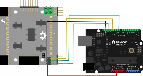
Wiring Diagram
Other Preparation Work
- Install the required library (rgb_matrix.h) in the Arduino IDE.
- Connect 8 pieces of 8x8 RGB Matrix in 4x2 arrangement to Arduino UNO according to the wiring diagram.
- Open the Arduino IDE and load the sample code.
- Select the correct board (Arduino UNO) and port in the Arduino IDE.
Sample Code
/*****************************************************************************
*                Copyright:  ChengDu Geeker Tech. Co., Ltd.
* File name:      hello_matrix.pde
* Description:    test the function of rgb matrix
* Author:       wanghui_CD
* Version:      V1.0
* Date:         2012.06.21
* History:      none
*****************************************************************************/
#include <rgb_matrix.h>
#include <SPI.h>

unsigned long time=0;
unsigned int tick_100ms = 0;
unsigned char counter=0;

#define N_X 4
#define N_Y 2

/*
//Interface shield ShiftOut connector
#define DATA_PIN  9
#define CLK_PIN   3
*/
//Hardware SPI
#define DATA_PIN  11
#define CLK_PIN   13

#define LATCH_PIN 8

rgb_matrix M = rgb_matrix(N_X, N_Y, DATA_PIN, CLK_PIN, LATCH_PIN);
unsigned char data_buf[N_X*N_Y*8*3]={0};

/*
×ÝÏòÈ¡Ä££¬¸ßλÔÚÉÏ¡£
ÏÈ×óºóÓÒ£¬ÏÈÉϺóÏ¡£
*/
const char ni[] =
{
      0x02,0x04,0x1F,0xE0,0x02,0x04,0x18,0xF0,
      0x10,0x13,0x10,0x10,0x14,0x18,0x00,0x00,
      0x00,0x00,0xFF,0x00,0x00,0x10,0x20,0xC2,
      0x01,0xFE,0x00,0x80,0x60,0x30,0x00,0x00
};
const char hao[] =
{
      0x08,0x08,0x0F,0xF8,0x08,0x0F,0x01,0x41,
      0x41,0x41,0x47,0x49,0x51,0x63,0x01,0x00,
      0x02,0x44,0xA8,0x10,0x28,0xC6,0x00,0x00,
      0x02,0x01,0xFE,0x00,0x00,0x00,0x00,0x00
};

unsigned char cmd[50]={0},cmd_num=0;

void setup()
{
       Serial.begin(115200);
       delay(200);
}

/*************************************************************************
*  Description:
*                         display callback function
*        Receive AT comand via serial,and then run the right comand.
*        This function can be run in sweep interval.
*        Reduce delay time at function tail if screen blink.
*        Increase delay time at function tail if screen shows a double image.
* Param:   none
* Retval:  none
**************************************************************************/
void hook(void)
{
    int i = 0;
    unsigned long enter_time,exit_time;
    enter_time = micros();
    //delayMicroseconds(300);
    if((++counter)%10 == 0)
    {
        if(millis() - time >= 100)
        {
            time = millis();
            tick_100ms ++;
            if(tick_100ms%2 == 0)
            {
            }
            if(tick_100ms%5 == 0)
            {
            }
            if(tick_100ms%10 == 0)
            {
                M.move(LEFT,1,0);
            }
            if(tick_100ms%20 == 0)
            {
                M.move(RIGHT,1,1);
            }
            if(tick_100ms%50 == 0)
            {
            }
        }
    }
    if(Serial.available())
    {
        cmd[cmd_num++] = Serial.read();
        if((cmd_num>=2) && (cmd[cmd_num-1] == 0x0a) && (cmd[cmd_num-2] == 0x0d))
        {
            M.at_cmd(cmd);
            cmd_num = 0;
        }
     }
     exit_time = micros();
     if(enter_time < exit_time)
     {
       if(exit_time - enter_time < 300)
       {
         delayMicroseconds(300 - (exit_time-enter_time));
       }
     }
}

/*************************************************************************************
*  Description:
*                         loop function
*        Display function must be called.
*        If you wanna do something after display be called,
*    you should give display function a parameter which is a pointer to a function.
* Param:   none
* Retval:  none
**************************************************************************************/
void loop()
{
    M.add_layer(data_buf);
    M.put_HZ(0,0,ni,MULTIPLY,RED+GREEN,TOP_LAYER);
    M.put_HZ(16,0,hao,MULTIPLY,GREEN,TOP_LAYER+1);
    M.display(hook);
}
Result
Expected phenomena: The 4x2 RGB matrix will display Chinese characters "Ni" (in red+green) and "Hao" (in green) moving left (layer 0) and right (layer 1) at different intervals. Users can also send AT commands via the serial port (baud rate 115200) to control the matrix, such as clearing the screen, moving layers, or displaying characters.
Additional Information
- Connection diagram for Arduino UNO:
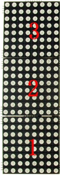
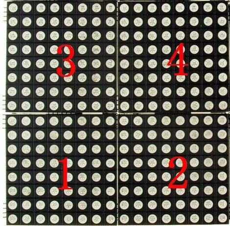
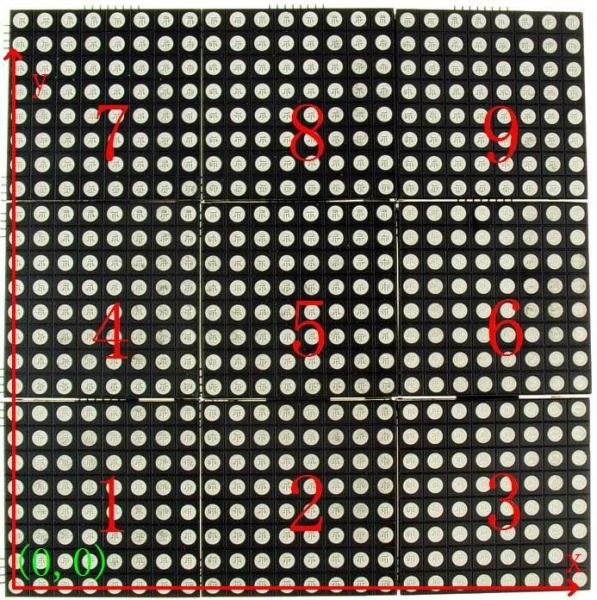
- Multiple modules connection:
Was this article helpful?