Example Code for Arduino-Output a Sine Wave
How to generate a sine wave using Arduino and MCP4725 DAC, detailing hardware/software setup, wiring, sample code, and results, enabling users to customize amplitude, frequency, and DC offset.
Hardware Preparation
- DFRduino UNO R3 + Gravity IO Expansion Shield * 1
- Gravity: MCP4725 12-Bit I2C DAC Module * 1
- Gravity 4P sensor wire (comes with Gravity 12-bit DAC Module) * 1
- Digital multimeter (optional) * 1
- Oscilloscope (optional) * 1
Software Preparation
- Arduino IDE: Click to Download Arduino IDE
- Search and install the 'DFRobot_MCP4725' library in the library manager of Arduino IDE.
- Or download the .zip library in via Github and install the .zip library in Arduino IDE. How to install .zip library?
Wiring Diagram

Other Preparation Work
- Set the I2C address to 0x60 with the ADDR switch. For I2C address 0x61, you need to modify the first parameter of the DAC.init () function in the code below.
- Open Arduino IDE, upload the following sample code to the Arduino UNO, and use a oscilloscope to measure the output voltage of VOUT.
- The user can modify the parameters in the function DAC.outputSin () to change the amplitude, frequency and DC offset of the sine wave.
Sample Code
/*
 * file OutputVoltage.ino
 *
 * @ https://github.com/DFRobot/DFRobot_MCP4725
 *
 * connect MCP4725 I2C interface with your board (please reference board compatibility)
 *
 * Output a constant voltage value and print through the serial port.
 *
 * Copyright   [DFRobot](https://www.dfrobot.com), 2016
 * Copyright   GNU Lesser General Public License
 *
 * version  V1.0
 * date  2018-1-25
 */
#include "DFRobot_MCP4725.h"
#define  REF_VOLTAGE    5000

DFRobot_MCP4725 DAC;

void setup(void) {
  Serial.begin(115200);
  /* MCP4725A0_address is 0x60 or 0x61
   * MCP4725A0_IIC_Address0 -->0x60
   * MCP4725A0_IIC_Address1 -->0x61
   */
  DAC.init(MCP4725A0_IIC_Address0, REF_VOLTAGE);
}

void loop(void) {
  /*Output a magnitude of 2500mv, the frequency of 10HZ, DC offset 2500mv sine wave*/
  DAC.outputSin(2500,10,2500);
}
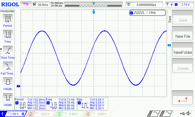
Result
- A full sine wave of 2.5V in amplitude (5V peak to peak), 10Hz and 2.5V DC bias can be observed.
Additional Information
/**
   * @fn outputSin
   * @brief  Output a sine wave.
   * @param  amp amp value, output sine wave amplitude range 0-5000mv
   * @param  freq freq value, output sine wave frequency
   * @param  offset offset value, output sine wave DC offset
   * @return None
   */
  void outputSin(uint16_t amp, uint16_t freq, uint16_t offset);

Was this article helpful?