WIAnode Quick Start
Last revision 2026/04/17
Usage Process
Configuration Phase

Yellow breathing light: Waiting for network configuration.
Red breathing light: Waiting for network connection.
Green breathing light: Network connected.
-
Power Supply: Connect the WIAnode to your computer using a Type-C data cable. At this point, Wi-Fi information has not been configured, and the status LED is yellow.
-
Quick Network Configuration:
-
A USB drive will appear on your computer. Open the
config.txtfile. (The name of the USB drive may vary; this does not affect functionality. You can keep it consistent by updating the firmware.) -
Configure the Wi-Fi SSID, password, and port settings. (Only 5G & 2.4G hybrid mode or 2.4G-only Wi-Fi networks are supported.)
-

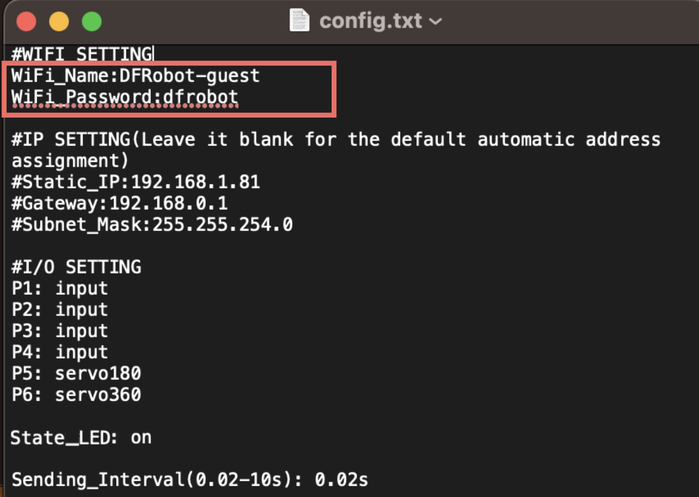
     	#WIFI SETTING
     	WiFi_Name:yourwifiname
     	WiFi_Password:yourwifipassword
- After saving the configuration file, the status LED turns red, indicating that the Wi-Fi configuration has been saved but the network is not yet connected.
Apply Configuration: Power cycle the WIAnode. The configuration will be automatically updated and it will connect to the Wi-Fi network.
- Once successfully connected to Wi-Fi, the IP address will be displayed on the screen, and the status LED will turn green.
Note:
If the yellow LED continues breathing:
- Please configure the Wi-Fi SSID and password for the device.
If the red LED continues breathing:
- Check whether the Wi-Fi SSID and password are entered correctly.
- Ensure that you are connecting to a 2.4GHz Wi-Fi network.
- If the credentials are correct, try power cycling the device.
Usage Phase
1. Detailed Configuration File Functions
Custom IP Settings:
	#IP SETTING(Leave it blank for the default automatic address asignment)
	Static_IP:192.168.xxx.xxx
	Gateway:192.168.1.1
	Subnet_Mask:255.255.255.0
Port Settings:
	#I/O SETTING
	P1: ws2812
	P2: ws2812
	P3: ws2812
	P4: input
	P5: servo180
	P6: servo360
Ports are divided into four categories:
(1) P1-P4: I/O Ports (3-wire)
- Usage: Four configuration tags available:
input/dht11/ds18b20/ws2812 - Refer to the sensor support list below for the corresponding tag for each sensor.
- Enter the corresponding tag in the port configuration field.
(2) P5-P6: 5V Servo Ports (3-wire)
- Usage: Three configuration tags available:
servo180/servo300/servo360 - Refer to the sensor support list below for the corresponding tag for each servo.
- Enter the corresponding tag in the port configuration field.
(3) I2C × 2: I2C Sensor Ports (4-wire)
- Usage: No configuration tag required. Simply connect the sensor, and it will be automatically configured. If correctly recognized, the sensor address will be displayed on the screen.
(4) Status LED Settings:
Sending_Interval(0.02-10s): 0.02s
(4) Status LED Settings:
- The WIAnode has a status LED on the side. If the status indicator light is not needed in actual use or deployment scenarios, it can be turned off via this configuration item.
(5) Sending Interval Settings:
LED_State: on
- LED_State: This configuration item controls the onboard status LED. Enter
onto turn it on, oroffto turn it off.
2. Screen Functions
- Press the WKUP button on the side to wake the screen and display the current device IP address.
- While the screen is on, press the button again to turn the page and display the current configuration status of each port.
3. MQTT Client Configuration
- IP Address: Enter the IP address displayed on the WIAnode screen.
- MQTT Configuration: Enter the fixed username and password directly.
User Name:wianode
Password:dfrobot
Firmware Update
- Drag the new firmware file into the configuration USB drive.
- Power cycle the WIAnode.
- Wait approximately 30 seconds for the firmware to refresh (the LED breathing normally indicates the update is complete).
Note: During firmware updates, frequent reconnection is normal. Do not disconnect power. Wait until the screen displays "dfrobot dfr1234" again, indicating the firmware update is complete.
Data Packet Format Description
1. Subscribe Topic: topic_input
JSON data packet format:
{"name_data1": value, "name_data2": value, ...}
Example: P1 connected to a button, P2 connected to a DHT11 sensor
Subscribed data packet content:
{"p1_input_val": 1, "p2_dht11_temp": 23, "p2_dht11_humi": 88}
- Publish Topic: topic_output
Format for publishing data to control ports:
{"name_data": value}
Example: I/O 1 connected to an LED strip, sending RGB values (rgb1, rgb2, rgb3...)
Control data content:
{"p1": "0 29 29 255 4 12 27 255 11"}
Was this article helpful?