Reference
This article details the communication protocols for operating motors, including UART interface parameters, command structures, operation steps, and protection regulations to ensure safe and efficient motor operation.
Communication Protocol Description
Basic Protocol Parameters
| Interface | Baud rate | Data bit | Stop bit | Parity bit | Data length |
|---|---|---|---|---|---|
| UART | 115200 | 8bit | 1bit | None | 10byte |
Key Specifications
Response format: One question and one answer
Rate: Up to 500Hz
In speed loop mode: -2100 ~ 2100 corresponds to -210rpm ~ 210rpm, data type is signed 16 bits
In position loop mode: 0 ~ 32767 corresponds to 0° ~ 360°, data type is unsigned 16 bits
Operation steps:
①Set motor ID (save when power off)
②Set motor mode (open loop, speed loop, position loop, default is speed loop)
③Send given value
Detailed Communication Commands
1. Drive the motor to rotate
Send to the motor:
| Data domain | DATA[0] | DATA[1] | DATA[2] | DATA[3] | DATA[4] | DATA[5] | DATA[6] | DATA[7] | DATA[8] | DATA[9] |
|---|---|---|---|---|---|---|---|---|---|---|
| Content | ID | 0x64 | Speed/position given high 8 bits | Speed/position given low 8 bits | 0 | 0 | Acceleration time | Braking | 0 | CRC8 |
Motor feedback:
| Data domain | DATA[0] | DATA[1] | DATA[2] | DATA[3] | DATA[4] | DATA[5] | DATA[6] | DATA[7] | DATA[8] | DATA[9] |
|---|---|---|---|---|---|---|---|---|---|---|
| Content | ID | 0x64 | Speed high 8 bits | Speed low 8 bits | Current high 8 bits | Current low 8 bits | Acceleration time | Temperature | Fault code | CRC8 |
Acceleration time: valid in speed loop mode, acceleration time per 1rpm, unit is 1ms, when set to 1, acceleration time per 1rpm is 1ms, when set to 10, acceleration time per 1rpm is 10*1ms=10ms, when set to 0, the default is 1, acceleration time per 1rpm is 1ms
Winding temperature: unit ℃
Brake: 0XFF Other values do not brake, valid in speed loop mode
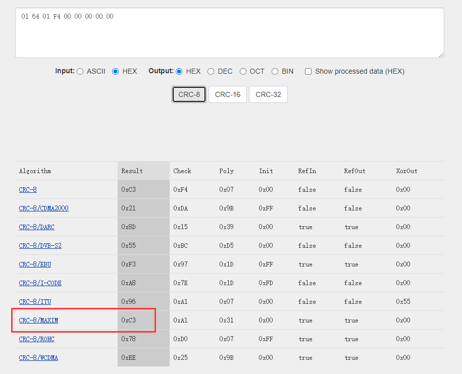
CRC8 value:
The value after CRC8 check of DATA[0]~DATA[8].
CRC algorithm: CRC-8/MAXIM
Polynomial: x8 + x5 + x4 +1
You can calculate the check digit through this website: https://crccalc.com/
For example: 01 64 01 F4 00 00 00 00 00 C3 (50rpm)
2. Get other feedback
Send to the motor:
| Data Field | DATA[0] | DATA[1] | DATA[2] | DATA[3] | DATA[4] | DATA[5] | DATA[6] | DATA[7] | DATA[8] | DATA[9] |
|---|---|---|---|---|---|---|---|---|---|---|
| Content | ID | 0x74 | 0 | 0 | 0 | 0 | 0 | 0 | 0 | CRC8 |
Motor feedback:
| Data field | DATA[0] | DATA[1] | DATA[2] | DATA[3] | DATA[4] | DATA[5] | DATA[6] | DATA[7] | DATA[8] | DATA[9] |
|---|---|---|---|---|---|---|---|---|---|---|
| Content | ID | 0x74 | Mileage lap high 8 bits | Mileage lap second high 8 bits | Mileage lap second low 8 bits | Mileage lap low 8 bits | Position high 8 bits | Position low 8 bits | Fault code | CRC8 |
Mileage lap: lap range - 2,147,483,647 to 2,147,483,647, reset to 0 after power on
Position value: 0 ~ 32767 corresponds to 0 ~ 360°
Fault code:
| Fault code | BIT7 | BIT6 | BIT5 | BIT4 | BIT3 | BIT2 | BIT1 | BIT0 |
|---|---|---|---|---|---|---|---|---|
| Content | Reserved | Over/under voltage fault | Reserved | Overtemperature fault | Stall fault | Reserved | Overcurrent fault | Hall fault |
For example, the fault code is: 0x02, which is 0b00000010, indicating an overcurrent fault
3. Motor mode switching
Sent to the motor:
| Data domain | DATA[0] | DATA[1] | DATA[2] | DATA[3] | DATA[4] | DATA[5] | DATA[6] | DATA[7] | DATA[8] | DATA[9] |
|---|---|---|---|---|---|---|---|---|---|---|
| Content | ID | 0xA0 | Mode value | 0 | 0 | 0 | 0 | 0 | 0 | CRC8 |
Motor feedback:
| Data domain | DATA[0] | DATA[1] | DATA[2] | DATA[3] | DATA[4] | DATA[5] | DATA[6] | DATA[7] | DATA[8] | DATA[9] |
|---|---|---|---|---|---|---|---|---|---|---|
| Content | ID | 0xA0 | Mode value | 0 | 0 | 0 | 0 | 0 | 0 | CRC8 |
Mode value:
0x00: Set to open loop
0x02: Set to speed loop
0x03: Set to position loop
4. Motor ID setting
Send to motor:
| Data field | DATA[0] | DATA[1] | DATA[2] | DATA[3] | DATA[4] | DATA[5] | DATA[6] | DATA[7] | DATA[8] | DATA[9] |
|---|---|---|---|---|---|---|---|---|---|---|
| Content | 0xAA | 0x55 | 0x53 | ID | 0 | 0 | 0 | 0 | 0 | CRC8 |
Motor feedback:
| Data field | DATA[0] | DATA[1] | DATA[2] | DATA[3] | DATA[4] | DATA[5] | DATA[6] | DATA[7] | DATA[8] | DATA[9] |
|---|---|---|---|---|---|---|---|---|---|---|
| Content | ID | 0x64 | 0 | 0 | 0 | 0 | 0 | 0 | 0 | CRC8 |
Note: When setting the ID, please ensure that there is only one motor on the bus. Only one setting is allowed per power-on. The motor will be set after receiving 5 ID setting instructions.
5. Get mode feedback
Send to motor:
| Data field | DATA[0] | DATA[1] | DATA[2] | DATA[3] | DATA[4] | DATA[5] | DATA[6] | DATA[7] | DATA[8] | DATA[9] |
|---|---|---|---|---|---|---|---|---|---|---|
| Content | ID | 0x75 | 0 | 0 | 0 | 0 | 0 | 0 | 0 | CRC8 |
Motor feedback:
| Data field | DATA[0] | DATA[1] | DATA[2] | DATA[3] | DATA[4] | DATA[5] | DATA[6] | DATA[7] | DATA[8] | DATA[9] |
|---|---|---|---|---|---|---|---|---|---|---|
| Content | ID | 0x75 | Mode value | 0 | 0 | 0 | 0 | 0 | 0 | CRC8 |
0x00: Open loop
0x02: Speed loop
0x03: Position loop
6. Get version number feedback
Send to motor:
| Data field | DATA[0] | DATA[1] | DATA[2] | DATA[3] | DATA[4] | DATA[5] | DATA[6] | DATA[7] | DATA[8] | DATA[9] |
|---|---|---|---|---|---|---|---|---|---|---|
| Content | ID | 0xFD | 0 | 0 | 0 | 0 | 0 | 0 | 0 | CRC8 |
Motor feedback:
| Data field | DATA[0] | DATA[1] | DATA[2] | DATA[3] | DATA[4] | DATA[5] | DATA[6] | DATA[7] | DATA[8] | DATA[9] |
|---|---|---|---|---|---|---|---|---|---|---|
| Content | ID | 0xFD | Year | Month | Day | Motor Model | Software Version | Hardware Version | Reserved | CRC8 |
Year/Month/Day: By default, 20 of 20XX is omitted, for example: 2021 is 0x15, November is 0x0B, and the 28th is 0x1C
UART Instruction Set
- Switch speed loop (02), this instruction has no feedback
01 A0 02 00 00 00 00 00 00 E4 - Get motor mode
01 75 00 00 00 00 00 00 00 47 - Brake command, valid in speed loop mode
01 64 00 00 00 00 00 FF 00 D1 - ID setting (01), send this command five times in a row
AA 55 53 01 00 00 00 00 00 00 - ID query
C8 64 00 00 00 00 00 00 00 DE - Speed loop command (-2100 ~ 2100 corresponds to -210~210 rpm)
01 64 FE 0C 00 00 00 00 00 16 (-50rpm) // Calculation method: FFFF-01F4+1=FE0C, reverse other speeds and so on
01 64 FC 18 00 00 00 00 00 EB (-100rpm)
01 64 F8 30 00 00 00 00 00 08 (-200rpm)
01 64 00 00 00 00 00 00 00 50 (0rpm)
01 64 01 F4 00 00 00 00 00 C3 (50rpm) //Calculation method: 50rpm=500=01F4, and the same applies to other speeds in forward rotation
01 64 03 E8 00 00 00 00 00 9F (100rpm)
01 64 07 D0 00 00 00 00 00 27 (200rpm) - Position loop command (0-32767 corresponds to 0-360°)
01 64 00 00 00 00 00 00 00 50 (0°)
01 64 20 00 00 00 00 00 00 BF (90°)//Calculation method: 90°=32767/360*90= ( Integer ) 8192(0x2000), and the same applies to other angles
01 64 40 00 00 00 00 00 00 97 (180°)
01 64 60 00 00 00 00 00 00 78 (270°)
01 64 7F FF 00 00 00 00 00 97 (360°)
Protection regulations
-
Bus overcurrent protection threshold: 2.8A, overcurrent duration exceeds 5S to trigger shutdown protection, and is released after 5S
-
Motor overtemperature protection threshold:
- 80℃, shutdown protection is triggered when the temperature is higher than 80℃, and protection is automatically released when it is lower than the threshold by 5℃
- -25℃, shutdown protection is triggered when the temperature is lower than -25℃, and protection is automatically released when it is higher than the threshold by 5℃
-
Stall protection: protection is triggered when the stall duration exceeds 5S, and is released after 5S
-
Overvoltage protection threshold:
- 28V, shutdown protection is triggered when the voltage is higher than 28V, and protection is automatically released when it is lower than the threshold by 0.5V
- 9V, shutdown protection is triggered when the voltage is lower than 9V, and protection is automatically released when it is higher than the threshold by 0.5V
Was this article helpful?