Reference
Last revision 2026/01/18
This article is a comprehensive resource on the DFRobot HX711 I2C library for Arduino, detailing installation, communication protocols, API functionalities, assembly instructions, and calibration techniques to maximize the utility of the HX711 weight sensor kit.
Library
- DFRobot HX711 I2C Library: Arduino library for the Gravity: HX711 Weight Sensor Kit. Includes functions for calibration, weight reading, and configuration
- Installation: Download the library from GitHub and install it via Arduino IDE (Sketch > Include Library > Add .ZIP Library)
Communication Protocol Description
- Communication Method: I2C
- I2C Addresses: 0x64 (A0=0, A1=0), 0x65 (A0=1, A1=0), 0x66 (A0=0, A1=1), 0x67 (A0=1, A1=1)
- Note: After the address is modified, it will take effect after the sensor is powered off and restarted
API Description
Common API functions for the DFRobot_HX711_I2C library:
/*!
   * @brief Constructor
   * @param pWire I2c controller
   * @param addr  I2C address(0x64/0x65/0x660x67)
   */
  DFRobot_HX711_I2C(TwoWire * pWire = &Wire,uint8_t addr = HX711_I2C_ADDR);

  /**
   * @brief Initialize function
   * @return Return 1 when initialization succeeds. Otherwise, return error code
   */
  int begin(void);

  /**
   * @brief Get object weight
   * @param The number of time to take avereage
   * @return Return the obtained weight,Unit: g
   */
  float readWeight(uint8_t times = 12);

  /**
   * @brief Get calibration value
   * @return Return the obtained calibration value
   */
  float getCalibration();

  /**
   * @brief Set/update calibration value
   * @param Value
   */
  void  setCalibration(float value);

  /**
   * @brief Set the sensor auto-calibration trigger threshold(g)
   * @param Threshold data
   */
  void  setThreshold(uint16_t threshold);

  /**
   * @brief Set the sensor calibration weight for auto-calibration(g)
   * @param Weight data
   */
  void  setCalWeight(uint16_t triWeight);

  /**
   * @brief Enable calibration (by software)
   */
  void enableCal();

  /**
   * @brief Tare (by software)
   */
  void peel();

  /**
   * @brief Wait for the sensor to complete calibration
   * @return Calibation completed, return: True
   *         Calibration failed, return: False
   */
  bool getCalFlag();
Other Supplementary Information
-
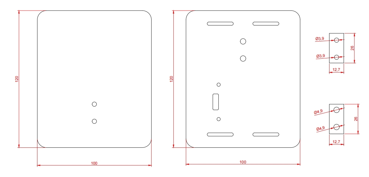
Assembly Steps:
- Fix the adapter board on the base with 3MM screws, and pass the 5mm screws through the bottom plate and the gasket with 5mm aperture.
- Fix the weighing rod and gasket on the base, connect the board and the sensor, note that the sticker with the green arrow should be downward.
- Pass the 4mm screw through the top plate and the spacer with 4mm hole diameter.
- Fix the top plate and gasket on the weighing beam, and finally paste the gasket on the bottom plate.
-
Operation Instruction:
- During calibration and measurement, the most accurate data will be obtained when the object is placed in the middle area of the scale.
- After pressing the rst key, no matter how many objects are placed on the sensor, the sensor will clear the current weight value, and the weight of the objects placed later will accumulate from 0, thus achieving the "tare" function.
- Every time you reset/restart the Arduino or open the serial port monitor, the system will "tare" once by default.
- The sensor calibration method: put an object of known weight on the sensor, and then "tell" the sensor what the weight of the object is, then the sensor will be calibrated (single-point calibration).
-
More Documents:
Was this article helpful?