Reference
The article explains the ModBus-RTU communication protocol, outlining communication parameters, data frame formats, and examples for sensor data reading, complemented by installation guidelines.
Communication Protocol Description
1. Basic communication parameters
| Interface | Encoding | Data bits | Parity bits | Stop bits | Error checking | Baud rate |
|---|---|---|---|---|---|---|
| RS485 | 8-bit binary | 8 | None | 1 | CRC | 2400bit/s, 4800bit/s, 9600 bit/s configurable, default 9600bit/s |
2. Data frame format definition
Using ModBus-RTU communication protocol, the format is as follows:
- Time for initial structure ≥4 bytes
- Address code = 1 byte
- Function code = 1 byte
- Data area = N bytes
- Error checking = 16-bit CRC code
- Time to end structure ≥4 bytes
- Address code: It is the address of the sensor, which is unique in the communication network (factory default 0x01).
- Function code: Function indication of the command sent by the host. This sensor reads the register function code 0x03 and writes the register function code 0x06
- Data area: The data area is specific communication data. Note that the high byte of 16bits data is first!
- CRC code: two-byte check code.
Host query frame structure:
| Address code | Function code | Register starting address | Register length | Check code low bit | Check code high bit |
|---|---|---|---|---|---|
| 1byte | 1byte | 2byte | 2byte | 1byte | 1byte |
Slave response frame structure:
| Address code | Function code | Number of valid bytes | Data area 1 | Data area 2 | Nth data area | Check code |
|---|---|---|---|---|---|---|
| 1byte | 1byte | 1byte | 2byte | 2byte | 2byte | 2byte |
3. Communication protocol examples and explanations
3.1. Example: Read the temporary value of nitrogen content at device address 0x01
Inquiry frame (hexadecimal):
| Address code | Function code | Register starting address | Register length | Check code low bit | Check code high bit |
|---|---|---|---|---|---|
| 0x01 | 0x03 | 0x00 0x1E | 0x00 0x01 | 0xE4 | 0x0C |
Response frame (hexadecimal):
| Address code | Function code | Return the number of valid bytes | Nitrogen temporary storage value | Low bit of check code | High bit of check code |
|---|---|---|---|---|---|
| 0x01 | 0x03 | 0x02 | 0x00 0x20 | 0xB9 | 0x9C |
Calculation of temporary nitrogen content value:
- Temporary storage value of nitrogen content: 0020 H (hexadecimal) = 32 => Nitrogen = 32mg/kg
3.2. Example: Read the temporary value of phosphorus content at device address 0x01
Inquiry frame (hexadecimal):
| Address code | Function code | Register starting address | Register length | Check code low bit | Check code high bit |
|---|---|---|---|---|---|
| 0x01 | 0x03 | 0x00 0x1F | 0x00 0x01 | 0xB5 | 0xCC |
Response frame (hexadecimal):
| Address code | Function code | Return the number of valid bytes | Temporary value | Low bit of check code | High bit of check code |
|---|---|---|---|---|---|
| 0x01 | 0x03 | 0x02 | 0x00 0x25 | 0x79 | 0x9F |
Calculation of temporary value of phosphorus content:
- Temporary value of phosphorus content: 0025 H (hexadecimal) = 37 => Phosphorus = 37mg/kg
3.3. Example: Read the temporary value of potassium content at device address 0x01
Inquiry frame (hexadecimal):
| Address code | Function code | Register starting address | Register length | Check code low bit | Check code high bit |
|---|---|---|---|---|---|
| 0x01 | 0x03 | 0x00 0x20 | 0x00 0x01 | 0x85 | 0xC0 |
Response frame (hexadecimal):
| Address code | Function code | Return the number of valid bytes | Temporary storage value | Low bit of check code | High bit of check code |
|---|---|---|---|---|---|
| 0x01 | 0x03 | 0x02 | 0x00 0x30 | 0xB8 | 0x50 |
Calculation of temporary value of potassium content:
- Temporary value of potassium content: 0030 H (hexadecimal) = 48 => Potassium = 48mg/kg
4. Register address
| Register address | PLC or configuration address | Content | Operation | Definition description |
|---|---|---|---|---|
| 001EH | 40031 (decimal) | Temporary nitrogen content value | Read and write | The written nitrogen content value or test value |
| 001FH | 40032 (decimal) | Temporary value of phosphorus content | Read and write | The written phosphorus content value or test value |
| 0020H | 40033 (decimal) | Potassium content temporary value | Read and write | The written potassium content value or test value |
| 03E8H | 41001 (decimal) | Temporary value of nitrogen content High sixteen digits of coefficient | Read and write | Floating point number |
| 03E9H | 41002 (decimal) | The lower sixteen digits of the nitrogen content temporary value coefficient | Read and write | Floating point number |
| 03EAH | 41003 (decimal) | Deviation value of the temporary value of nitrogen content | Read and write | Integer |
| 03F2H | 41011 (decimal) | Temporary storage value of phosphorus content High sixteen digits of coefficient | Read and write | Floating point number |
| 03F3H | 41012 (decimal) | The lower sixteen digits of the coefficient of the temporary storage value of phosphorus content | Read and write | Floating point number |
| 03F4H | 41013 (decimal) | Deviation value of the temporary value of phosphorus content | Read and write | Integer |
| 03FCH | 41021 (decimal) | Potassium content temporary value coefficient high sixteen digits | Read and write | Floating point number |
| 03FDH | 41022 (decimal) | The lower sixteen digits of the potassium content temporary value coefficient | Read and write | Floating point number |
| 03FEH | 41023 (decimal) | Deviation value of the temporary value of potassium content | Read and write | Integer |
| 07D0H | 42001 (decimal) | Device address | Read and write | 1-254 (factory default 1) |
| 07D1H | 42002 (decimal) | Device baud rate | Read and write | 0 represents 2400 1 represents 4800 2 represents 9600 |
Other Supplementary Information
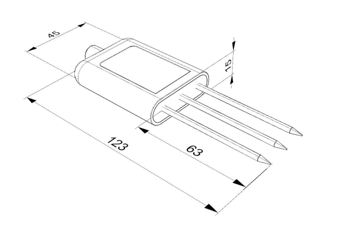
Dimensional Drawing
How to Install and Use
-
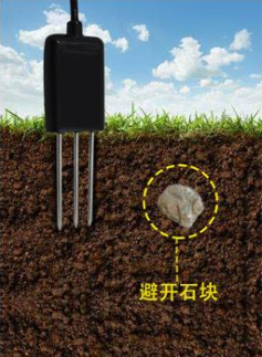
Quick Test Method
Select a stone-free location. Remove topsoil to the desired depth, keeping the lower soil compact. Hold the sensor vertically and insert it into the soil (do not wiggle). Measure multiple times at the same point and average the results.
-
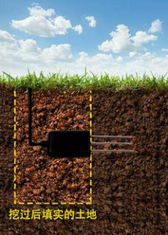
Buried Measurement Method
Dig a vertical pit (diameter >20cm). Insert the sensor’s steel needle horizontally into the pit wall at the desired depth. Fill the pit and wait for stabilization before long-term monitoring.
-
Things to Note
- Fully insert the steel needle into the soil during measurement.
- Avoid direct sunlight; protect from lightning in fields.
- Do not bend the steel needle or pull the cable forcefully.
- The sensor is IP68-rated (submersible), but avoid prolonged air power-on (due to RF interference).
Was this article helpful?