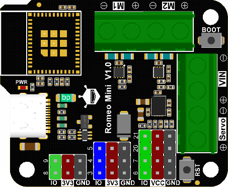
Romeo ESP32-C3-MINI-1 Motor & Servo Control Board

SKU: DFR1063

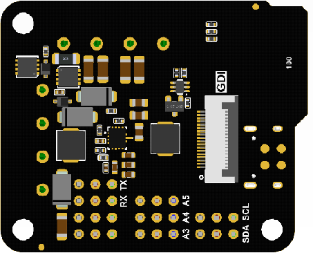
The Romeo mini robot controller is the ESP32 version of Romeo BLE mini, using an onboard ESP32-C3 module (Wi-Fi + Bluetooth 5). It has 2-channel 1.7A motor drivers, 9 IO interfaces (analog/digital/UART/I2C, Gravity-compatible), a servo power port, and a back GDI interface for IPS displays. It meets robot motor and servo control needs.

Board Overview of Romeo ESP32-C3 Mini Robot Controller

Downloadable Resources

  • Docs
  • Tech Specs
  • 1. Example Code for Arduino-PWM-driven DC Motors

    This project demonstrates how to use PWM signals to control the direction and speed of DC motors connected to the Romeo Mini. By adjusting PWM values and direction pins, users can learn the basics of motor control, PWM application, and proper wiring for motor drivers.

    2. Example Code for Arduino-PWM-Driven Servo Motor

    This project shows how to use PWM to control a servo motor's rotation angle with the Romeo Mini. Users can learn servo control basics, PWM frequency configuration, and wiring for high-current peripherals.

    3. Example Code for Arduino-Driving an SPI Display

    This project demonstrates how to connect and drive an SPI IPS display with the Romeo Mini to show text. Users can learn SPI communication, display library usage, and wiring for display modules.

    Reference

    This reference guide covers the DFRobot_GDL library and communication protocols such as I2C, UART, and SPI, providing links to datasheets and schematics for enhanced understanding.

    Specification

    Basic Parameters

    Parameter Details
    Main control chip ESP32-C3-MINI-1
    Type-C input voltage 5V
    VIN input voltage 5-12V
    Motor output current 1.7A continuous drive current per channel
    Servo input voltage 5-12V
    Module size 47x38.5mm

    Interface Pins

    Interface Type Details
    Digital I/O x4
    Analog I/O x3
    UART x1
    I2C x1
    Motor x2
    GDI x1
    Type-C x1

    Pinout

    Pinout Pinout
    Name Function Description
    VIN Power input for motor driver and controller: 5-12V. This port must be connected for M1/M2 motors to work.
    Servo Power input for digital ports: 5-12V. If using high-current peripherals with voltage higher than 5V on digital output port (VCC end), connect to this interface to avoid damaging the Type-C USB port.
    M1/M2 Ports Two motor control ports:
    M1: GPIO1 (direction control), GPIO0 (PWM control)
    M2: GPIO10 (direction control), GPIO2 (PWM control)
    I2C Standard I2C interface: SDA (8), SCL (9), VCC (3.3V), GND
    A-3.3V-GND Standard analog interface:
    A (blue): analog ports 3, 4, 5
    3.3V (red): power supply positive terminal
    GND (black): power supply negative terminal
    D-VCC-GND Standard digital interface:
    D (green): digital ports 6, 7, 20, 21
    VCC (red): power supply positive terminal (When the Servo port is not powered, VCC is 5V; when the Servo port is powered, VCC is the input power for the Servo port.)
    GND (black): power supply negative terminal
    UART RX (20), TX (21), VCC (5V), GND
    Note: The UART interface shares two IO ports with servo ports, so UART cannot be used when servos are used.
    RST Controller reset button
    BOOT Controller download button

    FAQ

    • No Serial Output

      Solution

      Check if USB CDC is enabled.

      Use a different serial debugging tool to view the print information.

    • Burn Error


      Cause

      If the delay in the loop is too short or no delay is added, it can result in a timeout error during the burning process.

      Incorrectly calling certain functions can cause the computer to not recognize the USB connection.

      Solution

      Press and hold the BOOT button, then click the RST button, and finally release the BOOT button.

    Explore More Related Questions >

    Was this article helpful?

    TOP