Example Code for Reading Acceleration & gyroscope
Last revision 2026/01/19
This article explains how to use I2C-connected gyroscope and accelerometer sensors for precise angle measurement, addressing sensitivity challenges with angle correction and software filtering, and includes sample code for practical implementation.
Introduction
This project demonstrates how to obtain stable tilt angle measurements by fusing data from an ADXL345 accelerometer and an ITG3205 gyroscope via the I²C (IIC) bus. Raw sensor data is referenced to the X, Y, and Z axes, and coordinate-based angle conversion is applied. Due to the high sensitivity of accelerometers—where minor vibrations cause large fluctuations—a complementary approach using gyroscope integration with software-based Kalman filtering is implemented to achieve smoother and more reliable angle estimation. The final results are output to the Arduino Serial Monitor for real-time observation.
Hardware Preparation
- Arduino-compatible board with Atmega32U4 (e.g., Arduino Leonardo or MiniQ Plus)
- ADXL345 3-axis digital accelerometer module
- ITG3205 3-axis digital gyroscope module
- Breadboard and jumper wires
- USB cable for power and programming
- Optional: External power supply (if not using USB)
Note: Both sensors communicate via I²C, so they share the SDA (Data) and SCL (Clock) lines with the microcontroller.
Software Preparation
- Arduino IDE (version 1.8.0 or higher)
- Installed libraries:
- Built-in
Wire.hlibrary (for I²C communication) - No additional third-party libraries required
- Built-in
- Ensure correct board selection (e.g., “Arduino Leonardo”) in the IDE
- Serial Monitor configured to 9600 baud
Wiring Diagram
Both the ADXL345 and ITG3205 are connected to the same I²C bus:
| Sensor Pin | Arduino Pin |
|---|---|
| VCC | 3.3V or 5V* |
| GND | GND |
| SDA | SDA (Pin D2 on Leonardo) |
| SCL | SCL (Pin D3 on Leonardo) |
*: Verify voltage compatibility. The ADXL345 and ITG3205 typically operate at 3.3V logic. Use level shifters if powering from 5V.
The ITG3205’s AD0 pin should be tied to GND to set its I²C address to 0x68.
The ADXL345 uses the default I²C address 0x53.
#include <Wire.h>
#include <math.h>
#define DEVICE (0x53)    //ADXL345 device address
#define TO_READ (6)        //num of bytes we are going to read each time (two bytes for each axis)

// Gyroscope Sensor ITG3205
#define ITGAddress   0x68    //set ITG3205 I2C Address(AD0)
#define G_SMPLRT_DIV 0x15    //set register of sampling rate
#define G_DLPF_FS 0x16     // set register of range, low-pass filter band width and clock frequency #define G_INT_CFG 0x17     //set register of interrupt
#define G_PWR_MGM 0x3E    //set register of power management

float xGyro, yGyro, zGyro;      //store angular rate and temperature
int buff[6];                  //store 6 value of X/Y/Z axis with high and low order address  (two bytes for each axis)
byte buff1[6];
//  The offset of gyroscope sensor error correction
int g_offx = -35;
int g_offy = -9;
int g_offz = -30;

void writeRegister(int deviceAddress, byte address, byte val)
{
  Wire.beginTransmission(deviceAddress);
  Wire.write(address);
  Wire.write(val);
  Wire.endTransmission();
}

void readRegister(int deviceAddress, byte address)
{
  Wire.beginTransmission(deviceAddress);
  Wire.write(address);
  Wire.endTransmission();
  Wire.beginTransmission(deviceAddress);
  Wire.requestFrom(deviceAddress, 6);

  int i = 0;
  while(Wire.available())
  { buff[i++] = Wire.read(); }
  Wire.endTransmission();
}

void initGyro()
{
  /*****************************************
 * ITG3205
 * G_SMPLRT_DIV:sampling rate = 125Hz
 * G_DLPF_FS:+ - 2000 rad/s、low pass filter 5HZ、internal sampling rate 1kHz
 * G_INT_CFG:no interrupt
 * G_PWR_MGM:Power management setting: no reset、no sleep mode、no idle mode 、internal oscillator   ******************************************/

  writeRegister(ITGAddress, G_SMPLRT_DIV, 0x07); //set sampling rate
  writeRegister(ITGAddress, G_DLPF_FS, 0x1E); //set  range, low-pass filter band width and internal  sampling rate
  writeRegister(ITGAddress, G_INT_CFG, 0x00); //set  of interrupt (default value )
writeRegister(ITGAddress, G_PWR_MGM, 0x00);    //set power management (default value )

   //Turning on the ADXL345
   writeTo(DEVICE, 0x2D, 0);
   writeTo(DEVICE, 0x2D, 16);
   writeTo(DEVICE, 0x2D, 8);
}

float getGyroValues()
{
  readRegister(ITGAddress, 0x1D); //read gyroscope sensor data
  xGyro = ((buff[0] << 8) | buff[1]) + g_offx;
  yGyro = ((buff[2] << 8) | buff[3]) + g_offy;
  zGyro = ((buff[4] << 8) | buff[5]) + g_offz;

  return xGyro;
}

float getadxvalues()
{
  int regAddress = 0x32;    //first axis-acceleration-data register on the ADXL345
  int x, y, z;

 readFrom(DEVICE, regAddress, TO_READ, buff1); //read the acceleration data from the ADXL345
  //each axis reading comes in 10 bit resolution, ie 2 bytes.  Least Significat Byte first!!
  //thus we are converting both bytes in to one int
 x = (((int)buff1[1]) << 8) | buff1[0];
 y = (((int)buff1[3])<< 8) | buff1[2];
 z = (((int)buff1[5]) << 8) | buff1[4];

 float Rx = x * 0.0039 + 0.035;
 float Ry = y * 0.0039 + 0.035;
 float Rz = z * 0.0039 + 0.040;
// Rx = abs(Rx);
 float R = sqrt( Rx*Rx + Ry*Ry + Rz*Rz );
 float Axr = acos(Rx/R) * 57.2958;

 return Axr;
}

 //******Kalman filter************
float Gyro_y;        //temporary storage  of  gyroscope sensor data in Y axis
float Angle_gy;      //inclination angle calculated from angular rate
float Accel_x;             //temporary storage  of  accelermeter data in Y axis
float Angle_ax;      //inclination angle calculated from accelerator
float Angle;         //final inclination angle
//uchar value;                 //polarity mark of angle
float  Q_angle=0.001;
float  Q_gyro=0.003;
float  R_angle=0.5;
float  dt=0.01;                          //the sampling time of Kalman filter;
char   C_0 = 1;
float  Q_bias, Angle_err;
float  PCt_0, PCt_1, E;
float  K_0, K_1, t_0, t_1;
float  Pdot[4] ={0,0,0,0};
float  PP[2][2] = { { 1, 0 },{ 0, 1 } };
float kalmanUpdate(float Accel,float Gyro)
{
   Angle+=(Gyro - Q_bias) * dt; //priori estimate

   Pdot[0]=Q_angle - PP[0][1] - PP[1][0]; // differential of error covariance of priori estimate

   Pdot[1]=- PP[1][1];
   Pdot[2]=- PP[1][1];
   Pdot[3]=Q_gyro;

   PP[0][0] += Pdot[0] * dt;   // Integration of the differential of error covariance of priori estimate
   PP[0][1] += Pdot[1] * dt;   // error covariance of priori estimate
   PP[1][0] += Pdot[2] * dt;
   PP[1][1] += Pdot[3] * dt;

   Angle_err = Accel - Angle;        //priori estimate

   PCt_0 = C_0 * PP[0][0];
   PCt_1 = C_0 * PP[1][0];

   E = R_angle + C_0 * PCt_0;

   K_0 = PCt_0 / E;
   K_1 = PCt_1 / E;

   t_0 = PCt_0;
   t_1 = C_0 * PP[0][1];

   PP[0][0] -= K_0 * t_0;                 //error covariance of  posterior estimate
   PP[0][1] -= K_0 * t_1;
   PP[1][0] -= K_1 * t_0;
   PP[1][1] -= K_1 * t_1;

   Angle        += K_0 * Angle_err;         //posterior estimate
   Q_bias        += K_1 * Angle_err;         //posterior estimate
   Gyro_y   = Gyro - Q_bias;         //Output ( the differential of  posterior estimate ) = Angle rate
}

void setup()
{
  Serial.begin(9600);
  Wire.begin();
  initGyro();
  delay(50);
}


void loop()
{
  float Accel_x = getadxvalues();
  float Gyro_x = getGyroValues()/14.375;

  kalmanUpdate( Accel_x, Gyro_x );

  Angle = Angle + (((Accel_x-Angle)*0.5 + Gyro_y)*0.001);
  Serial.print(Accel_x);
  Serial.print("   ");
  Serial.println(Angle);
}

//---------------- Functions
//Writes val to address register on device
void writeTo(int device, byte address, byte val) {
  Wire.beginTransmission(device); //start transmission to device
  Wire.write(address);        // send register address
  Wire.write(val);        // send value to write
  Wire.endTransmission(); //end transmission
}

//reads num bytes starting from address register on device in to buff array
void readFrom(int device, byte address, int num, byte buff[])
{
 Wire.beginTransmission(device); //start transmission to device
 Wire.write(address);        //sends address to read from
 Wire.endTransmission(); //end transmission

 Wire.beginTransmission(device); //start transmission to device
 Wire.requestFrom(device, num);    // request 6 bytes from device

 int i = 0;
 while(Wire.available())    //device may send less than requested (abnormal)
 {
   buff[i] = Wire.read(); // receive a byte
   i++;
 }
 Wire.endTransmission(); //end transmission
}
Result
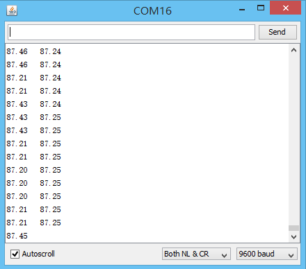
When the code runs, the Arduino continuously reads acceleration and angular rate data from the ADXL345 and ITG3205, respectively. The Kalman filter fuses these signals to produce a stable estimate of the tilt angle around the X-axis.
In the Serial Monitor (9600 baud), you will see two values printed every 10 ms:
Accel Angle: Raw angle derived solely from the accelerometer (noisy but drift-free).
Filtered Angle: Smooth, drift-corrected angle output from the Kalman filter.
Under static conditions, the filtered angle remains steady even when the board is gently tapped—demonstrating effective noise suppression while maintaining responsiveness to actual orientation changes.
Was this article helpful?