Example Code for Arduino-PID Speed Control
This project demonstrates how to use a PID algorithm to control the motor speed using an L298P motor driver. Users can learn how to implement closed-loop speed control to maintain a stable rotational speed.
Hardware Preparation
| Produce | Quantity |
|---|---|
| Arduino UNO | 1 |
| DC power supply | 1 |
| L298 2x2A Motor Shield for Arduino Twin | 1 |
Software Preparation
- Arduino IDE Download Arduino IDE
Wiring Diagram
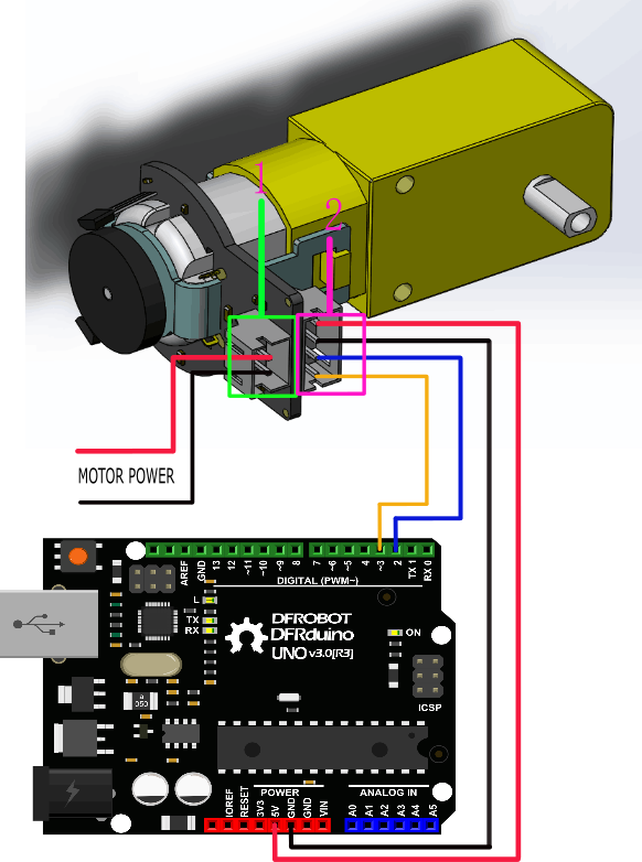
This tutorial is about Encoder usage. We are using D2&D3 as driving pins, you can select other ones, but it requires at least 1 interrupt pin. (We selected D2, Interrupt 0 in this tutorial).
Other Preparation Work
Notice: attachInterrupt()
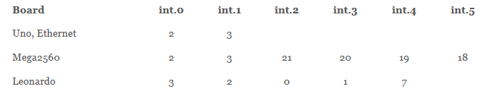
If using an Arduino UNO and you want to use interrupt port 0 (Int.0), you need to connect digital pin D2 on the board. The following code is only used in UNO and Mega2560. If you want to use Arduino Leonardo, you should change digital pin D3 instead of digital pin D2.
Sample Code
//The sample code for driving one way motor encoder
#include <PID_v1.h>
const byte encoder0pinA = 2;//A pin -> the interrupt pin 0
const byte encoder0pinB = 3;//B pin -> the digital pin 3
int E_left =5; //The enabling of L298PDC motor driver board connection to the digital interface port 5
int M_left =4; //The enabling of L298PDC motor driver board connection to the digital interface port 4
byte encoder0PinALast;
double duration,abs_duration;//the number of the pulses
boolean Direction;//the rotation direction
boolean result;

double val_output;//Power supplied to the motor PWM value.
double Setpoint;
double Kp=0.6, Ki=5, Kd=0;
PID myPID(&abs_duration, &val_output, &Setpoint, Kp, Ki, Kd, DIRECT);

void setup()
{
  Serial.begin(9600);//Initialize the serial port
   pinMode(M_left, OUTPUT);   //L298P Control port settings DC motor driver board for the output mode
   pinMode(E_left, OUTPUT);
   Setpoint =80;  //Set the output value of the PID
   myPID.SetMode(AUTOMATIC);//PID is set to automatic mode
   myPID.SetSampleTime(100);//Set PID sampling frequency is 100ms
  EncoderInit();//Initialize the module
}

void loop()
{
      advance();//Motor Forward
      abs_duration=abs(duration);
      result=myPID.Compute();//PID conversion is complete and returns 1
      if(result)
      {
        Serial.print("Pluse: ");
        Serial.println(duration);
        duration = 0; //Count clear, wait for the next count
      }


}

void EncoderInit()
{
  Direction = true;//default -> Forward
  pinMode(encoder0pinB,INPUT);
  attachInterrupt(0, wheelSpeed, CHANGE);
}

void wheelSpeed()
{
  int Lstate = digitalRead(encoder0pinA);
  if((encoder0PinALast == LOW) && Lstate==HIGH)
  {
    int val = digitalRead(encoder0pinB);
    if(val == LOW && Direction)
    {
      Direction = false; //Reverse
    }
    else if(val == HIGH && !Direction)
    {
      Direction = true;  //Forward
    }
  }
  encoder0PinALast = Lstate;

  if(!Direction)  duration++;
  else  duration--;

}
void advance()//Motor Forward
{
     digitalWrite(M_left,LOW);
     analogWrite(E_left,val_output);
}
void back()//Motor reverse
{
     digitalWrite(M_left,HIGH);
     analogWrite(E_left,val_output);
}

void Stop()//Motor stops
{
     digitalWrite(E_left, LOW);
}
Result
The code PID value has been set as 80, so the motor will stabilize at about 80 rpm. If outside forces such as changes in motor drive voltage, the motor's resistance, etc affect the speed, the program will adjust the PWM value to stabilize the rotational speed at 80.
Was this article helpful?