Example Code for Arduino-Acceleration Gyroscope
The project reads 3-axis gyroscope and 3-axis accelerometer data from the BMI160. Users can learn how to retrieve combined motion data from the sensor.
Hardware Preparation
- 1 x BMI160 6-axis IMU
- 1 x Arduino Uno
Software Preparation
Wiring Diagram
- Connect the BMI160 6-axis IMU to Arduino board by I2C (" "can connect "3V3" or "5V")
- Connect the INT1 or INT2 to the corresponding pins on the Arduino board, as shown in the following table
| Arduino board | Corresponding Pins |
|---|---|
| Arduino UNO | D2 |
| FireBeetle-ESP32 | D13 |
| FireBeetle-ESP8266 | D13 |
| FireBeetle-Board328P | D2 |
| Leonardo | D3 |
Connection Diagram 
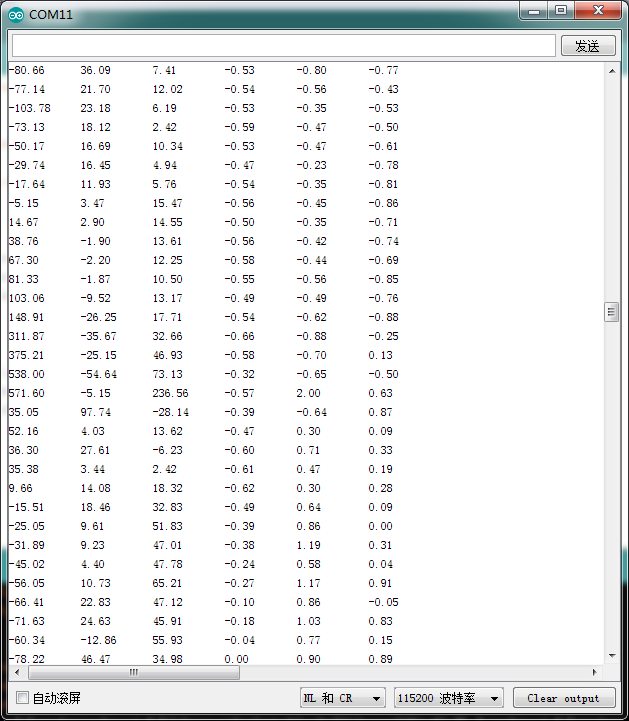
The first three columns are the data of the gyroscope in the direction of the X, Y, and Z axis, and the last three are the data of the acceleration in the direction of the X, Y, and Z axis.
Sample Code
#include "DFRobot_BMI160.h"

DFRobot_BMI160 bmi160;
const int8_t i2c_addr = 0x69;
void setup(){
  Serial.begin(115200);
  delay(100);

  //init the hardware bmin160
  if (bmi160.softReset() != BMI160_OK){
    Serial.println("reset false");
    while(1);
  }

  //set and init the bmi160 i2c address
  if (bmi160.I2cInit(i2c_addr) != BMI160_OK){
    Serial.println("init false");
    while(1);
  }
}

void loop(){
  int i = 0;
  int rslt;
  int16_t accelGyro[6]={0};

  //get both accel and gyro data from bmi160
  //parameter accelGyro is the pointer to store the data
  rslt = bmi160.getAccelGyroData(accelGyro);
  if(rslt == 0){
    for(i=0;i<6;i  ){
      if (i<3){
        //the first three are gyro datas
        Serial.print(accelGyro[i]*3.14/180.0);Serial.print("\t");
      }else{
        //the following three data are accel datas
        Serial.print(accelGyro[i]/16384.0);Serial.print("\t");
      }
    }
    Serial.println();
  }else{
    Serial.println("err");
  }
}
Result
The serial port will output 6 columns of data: the first three are gyroscope data (X, Y, Z axes) in radians per second, and the last three are accelerometer data (X, Y, Z axes) in g.
- Fig2: Gravity:BMI160 6-axis IMU Acceleration Gyroscope
Was this article helpful?