Example Code for Arduino-Obtain Sensor Analog Value
This project demonstrates how to obtain the sensor’s raw analog value. If you need to calculate gas concentration manually or apply your own temperature-compensation algorithm, upload the sample code to the Arduino UNO and open the Serial Monitor to view the original voltage output from the MiCS-4514 MEMS chip.
Hardware Preparation
- DFRuino UNO R3 x1
- SEN0377 Gravity MEMS Gas Sensor x1
- Dupont Wires
Software Preparation
- Arduino IDE Arduino IDE
- Download and install DFRobot_MICS Library (About how to install the library?)
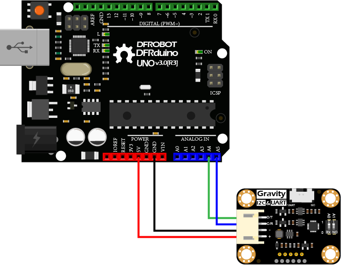
Wiring Diagram
Other Preparation Work
- Connect the module to the Arduino according to the wiring diagram above. You may also use a Gravity I/O adapter for faster and more convenient prototyping.
- Turn the selector switch to the I2C position.
- Verify or modify the I2C address:
- The default I2C address is 0x78, corresponding to ADDRESS_3 in the code.
- To change the address, adjust the DIP switch on the module, then update the corresponding
ADDRESS_Xdefinition in the code. - DIP switch and I2C address mapping:
- ADDRESS_0: 0x75 (A0=0, A1=0) — Default
- ADDRESS_1: 0x76 (A0=1, A1=0)
- ADDRESS_2: 0x77 (A0=0, A1=1)
- ADDRESS_3: 0x78 (A0=1, A1=1)
- Download and install the DFRobot_MICS library.
- Open Arduino IDE:
- Upload the sample code to the Arduino UNO, or
- Open getGasPPM.ino from the library examples and upload it.
- Open the Serial Monitor, set the baud rate to 115200, and observe the output.
Sample Code
 /*!
  * @file  getADCData.ino
  * @brief Reading MICS sensor ADC original value
  * @n When using IIC device, select I2C address, set the dialing switch A0, A1 (Address_0 is [0 0]), (Address_1 is [1 0]), (Address_2 is [0 1]), (Address_3 is [1 1]).
  * @n When using the Breakout version, connect the adcPin and PowerPin
  * @copyright   Copyright (c) 2010 DFRobot Co.Ltd (http://www.dfrobot.com)
  * @licence     The MIT License (MIT)
  * @author      ZhixinLiu([email protected])
  * @version     V1.1
  * @date        2021-04-19
  * @get         from https://www.dfrobot.com
  * @url         https://github.com/dfrobot/DFRobot_MICS
  */

#include "DFRobot_MICS.h"

// When using I2C communication, use the following program to construct an object by DFRobot_MICS_I2C
/**!
    iic slave Address, The default is ADDRESS_3
       ADDRESS_0               0x75             // i2c device address
       ADDRESS_1               0x76
       ADDRESS_2               0x77
       ADDRESS_3               0x78
*/
#define Mics_I2C_ADDRESS ADDRESS_3
DFRobot_MICS_I2C mics(&Wire, Mics_I2C_ADDRESS);

// When using the Breakout version, use the following program to construct an object from DFRobot_MICS_ADC
/**!
  adcPin is A0~A5
  powerPin is General IO
*/
#define ADC_PIN   A0
#define POWER_PIN 10
//DFRobot_MICS_ADC mics(/*adcPin*/ADC_PIN, /*powerPin*/POWER_PIN);

void setup()
{
  Serial.begin(115200);
  while(!Serial);
  while(!mics.begin()){
    Serial.println("NO Deivces !");
    delay(1000);
  } Serial.println("Device connected successfully !");

  /**!
    Gets the power mode of the sensor
    The sensor is in sleep mode when power is on,so it needs to wake up the sensor.
    The data obtained in sleep mode is wrong
   */
  uint8_t mode = mics.getPowerState();
  if(mode == SLEEP_MODE){
    mics.wakeUpMode();
    Serial.println("wake up sensor success!");
  }else{
    Serial.println("The sensor is wake up mode");
  }
}

void loop()
{
  int16_t ox_data  = 0;
  int16_t red_data = 0;
  /**!
    MICS-5524 Only OX_MODE ADC data can be obtained
    MICS-2714 Only RED_MODE ADC data can be obtained
    MICS-4514 Gravity can obtain AllMode ADC data
  */
  ox_data  = mics.getADCData(OX_MODE);
  //red_data = mics.getADCData(RED_MODE);
  Serial.print("ox  data = ");
  Serial.println(ox_data);
  //Serial.print("red data = ");
  //Serial.println(red_data);
  delay(1000);
}
Result
Open the serial port monitor and warm up for about 3 minutes, you can obtain the MEMS chip MiCS-4514 raw data.

Two detection units(ox and red) are integrated in MiCS-4514 to calculate the concentration data of different gas. For specific curves, please refer to the sensor data curve in the wiki.
The sensor takes 3 minutes to warm up.
Was this article helpful?