Example Code for Arduino-Get Sensor Analog Value
If you want to obtain the original sensor data, calculate the gas concentration or add your own temperature compensation functions, you can download the sample program to the Arduino UNO, open serial port monitor to view the original voltage output of the MEMS chip MiCS-2714.
Hardware Preparation
- DFRduino UNO R3 (or similar) x 1
- SEN0441 Fermion: MEMS Gas Sensor - MiCS-2714 x1
- M-M/F-M/F-F Jumper wires
Software Preparation
- Arduino IDE
- Download and install the DFRobot MICS Library. (About how to install the library?)
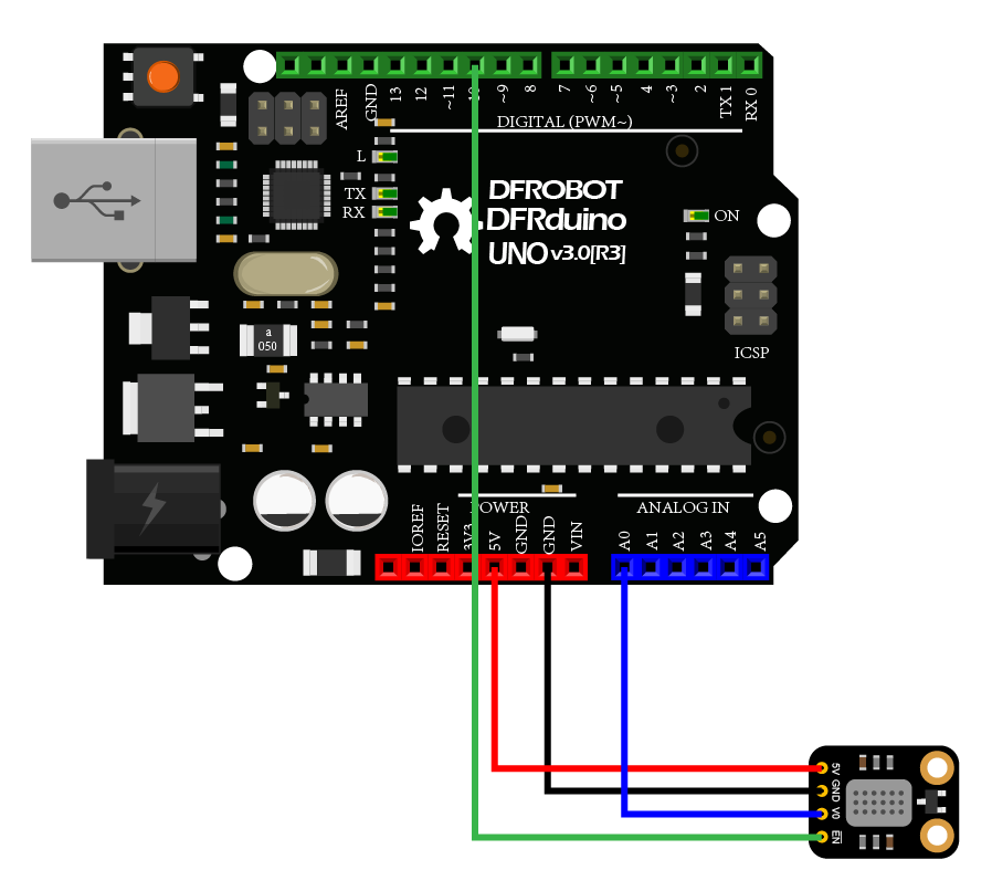
Wiring Diagram
Other Preparation Work
- Connect the module with Arduino according to the connection diagram above.
- Download and install the DFRobot MICS Library. (About how to install the library?)
- Open Arduino IDE
- Upload the following sample code to the Arduino UNO
- Or open the getGasExist.ino code in the library file sample, revise the configuration in the code (comment part of the I2C link code, uncomment the codes for breakout version), and change the gas type to NO2, then burn the modified code to the Arduino UNO
- Open the serial port monitor of the Arduino IDE, adjust the baud rate to 115200, and observe the print results.
Sample Code
/*!
  * @file  getADCData.ino
  * @brief Reading MICS sensor ADC original value
  * @n When using IIC device, select I2C address, set the dialing switch A0, A1 (Address_0 is [0 0]), (Address_1 is [1 0]), (Address_2 is [0 1]), (Address_3 is [1 1]).
  * @n When using the Breakout version, connect the adcPin and PowerPin
  * @copyright   Copyright (c) 2010 DFRobot Co.Ltd (http://www.dfrobot.com)
  * @licence     The MIT License (MIT)
  * @author      ZhixinLiu([email protected])
  * @version     V1.1
  * @date        2021-04-19
  * @get         from https://www.dfrobot.com
  * @url         https://github.com/dfrobot/DFRobot_MICS
  */

#include "DFRobot_MICS.h"

// When using the Breakout version, use the following program to construct an object from DFRobot_MICS_ADC
/**!
  adcPin is A0~A5
  powerPin is General IO
*/
#define ADC_PIN   A0
#define POWER_PIN 10
DFRobot_MICS_ADC mics(/*adcPin*/ADC_PIN, /*powerPin*/POWER_PIN);

void setup()
{
  Serial.begin(115200);
  while(!Serial);
  while(!mics.begin()){
    Serial.println("NO Deivces !");
    delay(1000);
  } Serial.println("Device connected successfully !");

  /**!
    Gets the power mode of the sensor
    The sensor is in sleep mode when power is on,so it needs to wake up the sensor.
    The data obtained in sleep mode is wrong
   */
  uint8_t mode = mics.getPowerState();
  if(mode == SLEEP_MODE){
    mics.wakeUpMode();
    Serial.println("wake up sensor success!");
  }else{
    Serial.println("The sensor is wake up mode");
  }
}

void loop()
{
  int16_t ox_data  = 0;
  int16_t red_data = 0;
  /**!
    MICS-5524 Only OX_MODE ADC data can be obtained
    MICS-2714 Only RED_MODE ADC data can be obtained
    MICS-4514 Gravity can obtain AllMode ADC data
  */
  ox_data  = mics.getADCData(OX_MODE);
  //red_data = mics.getADCData(RED_MODE);
  Serial.print("ox  data = ");
  Serial.println(ox_data);
  //Serial.print("red data = ");
  //Serial.println(red_data);
  delay(1000);
}
Result
Open the serial port monitor,warm up for about three minutes,and it's enable to you to obtain the original data.
Notes:
- Two detection units(ox and red) are integrated in MiCS-4514 to calculate the concentration data of different gas. For specific curves, please refer to the sensor data curve in the wiki.
- The sensor takes 3 minutes to warm up.

Was this article helpful?