Reference
The article explains RS485 communication protocol using ModBus-RTU, detailing data frame formats, register addresses, and installation for effective sensor data collection.
Communication Protocol Description
1. Basic communication parameters
| Interface | Encoding | Data bits | Parity bits | Stop bits | Error checking | Baud rate |
|---|---|---|---|---|---|---|
| RS485 | 8-bit binary | 8 | None | 1 | CRC | 2400bit/s, 4800bit/s, 9600 bit/s configurable, default 9600bit/s |
2. Data frame format definition
Using ModBus-RTU communication protocol, the format is as follows:
-
Time for initial structure ≥4 bytes
-
Address code = 1 byte
-
Function code = 1 byte
-
Data area = N bytes
-
Error checking = 16-bit CRC code
-
Time to end structure ≥4 bytes
-
Address code: Unique sensor address in the network (factory default: 0x01)
-
Function code: 0x03 (read register), 0x06 (write register)
-
Data area: Specific communication data (high byte first for 16-bit values)
-
CRC code: Two-byte checksum
Host query frame structure:
| Address code | Function code | Register starting address | Register length | Check code low bit | Check code high bit |
|---|---|---|---|---|---|
| 1byte | 1byte | 2byte | 2byte | 1byte | 1byte |
Slave response frame structure:
| Address code | Function code | Number of valid bytes | Data area 1 | Data area 2 | Nth data area | Check code |
|---|---|---|---|---|---|---|
| 1byte | 1byte | 1byte | 2byte | 2byte | 2byte | 2byte |
3. Communication protocol examples and explanations
Example: Read sensor data (address: 0x01)
- Inquiry frame (hex):
0x01 0x03 0x00 0x00 0x00 0x03 0x05 0xCB - Response frame (hex):
0x01 0x03 0x06 0x02 0x92 0xFF 0x9B 0x03 0xE8 0xD8 0x0F
Calculations:
- Humidity:
0x0292→ 658 → 65.8%RH - Temperature:
0xFF9B(two's complement) → -101 → -10.1°C - Conductivity:
0x03E8→ 1000 → 1000 μS/cm
4. Register address
| Register address | PLC or configuration address | Content | Operation | Definition description |
|---|---|---|---|---|
| 0000H | 40001 (decimal) | Moisture content | Read-only | Real-time value (expanded 10x) |
| 0001H | 40002 (decimal) | Temperature value | Read-only | Real-time value (expanded 10x) |
| 0002H | 40003(decimal) | Conductivity | Read-only | Real-time value |
| 0003H | 40004(decimal) | Salinity | Read-only | Real-time value |
| 0004H | 40005(decimal) | Total dissolved solids TDS | Read only | Real-time value |
| 0022H | 40035 (decimal) | Conductivity temperature coefficient | Read and write | 0-100 → 0.0%-10.0% (default: 0.0%) |
| 0023H | 40036 (decimal) | Salinity coefficient | Read and write | 0-100 → 0.00-1.00 (default: 55 → 0.55) |
| 0024H | 40037 (decimal) | TDS coefficient | Read and write | 0-100 → 0.00-1.00 (default: 50 → 0.5) |
| 0050H | 40081 (decimal) | Temperature calibration value | Read and write | Integer (expanded 10x) |
| 0051H | 40082 (decimal) | Moisture content calibration value | Read and write | Integer (expanded 10x) |
| 0052H | 40083(decimal) | Conductivity calibration value | Read and write | Integer |
| 07D0H | 42001 (decimal) | Device address | Read and write | 1-254 (default: 1) |
| 07D1H | 42002 (decimal) | Device baud rate | Read and write | 0→2400, 1→4800, 2→9600 |
Other Supplementary Information
How to install and use
-
Quick test method
Select a stone-free location, remove topsoil to the desired depth, insert the sensor vertically into the soil (avoid side-to-side movement), and take multiple measurements for averaging.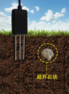
-
Buried measurement method
Dig a ≥20cm diameter pit, insert the sensor horizontally into the pit wall at the target depth, backfill tightly, and wait for stabilization before long-term monitoring.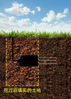
-
Things to note
- Ensure the steel needle is fully inserted into the soil.
- Avoid direct sunlight or lightning exposure.
- Do not bend the needle, pull the cable, or drop the sensor.
- IP68-rated: Can be submerged in water.
- Do not leave powered on in air for extended periods (RF interference).
Was this article helpful?