Getting Started
Last revision 2025/12/09
This article guides users through the initial setup of the Rainbow Ring V3, including soldering pin headers, installing the required libraries, and programming the board using Arduino, with emphasis on proper power supply and correct board configuration.
Version Notice (SKU: DFR0141)
This wiki page applies to Rainbow Ring V3, the latest hardware revision of this product.
Documentation for earlier revisions (V2) is provided in a separate legacy guide.
-
Hardware Preparation
The Rainbow Ring ships without pin headers, allowing you to solder the pins according to your project requirements.
Before programming the LED Ring, please solder the pin headers onto the board.Only supply power to one of the three power pins at any one time.
-
Download the Library
Download the library archive:
RAR File (New RAR file with additional sample code)This library has not yet been upgraded for compatibility with Arduino IDE V1.0.
Please use Arduino 0023. -
Change the Arduino Board Configuration
-
Step 1:
After downloading, unzip the files. You should see the following file structure: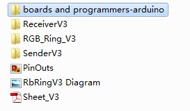
-
Step 2:
Open the following directory from the extracted files:boards and programmers-arduino/boards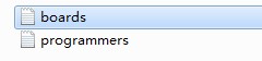
-
Step 3:
Open the Arduino 0023 hardware directory:Arduino 0023/hardware/arduino
-
Step 4:
Replace the boards folder in the Arduino 0023 directory with the boards folder from Step 2.
Then restart Arduino 0023 and select the following board:[Optiboot] Lilypad Arduino w/ ATmega168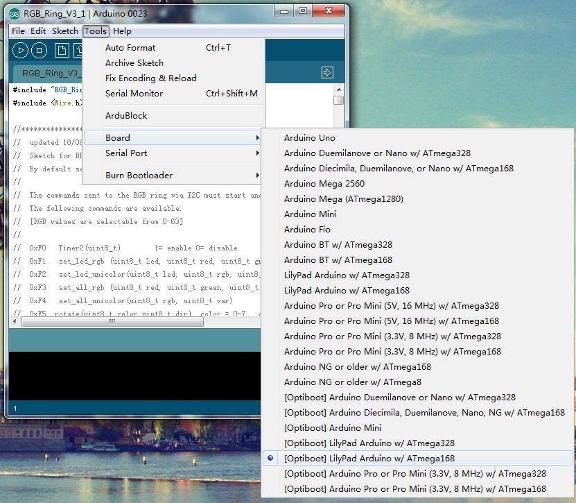
-
Was this article helpful?