Example Code for Arduino-Wakeup Function
Last revision 2026/01/19
This example uses the wake-up function. The module enters low-power mode with a reduced sampling rate and switches to normal mode when an interrupt is triggered.
Hardware Preparation
- DFRduino UNO R3 (or similar) x 1
- LIS331HH Triple Axis Accelerometer (Breakout Version) x1
- Jumper wires
Software Preparation
- Arduino IDE
- Download and install the LIS Series Library and Sample Code. (About how to install the library?)
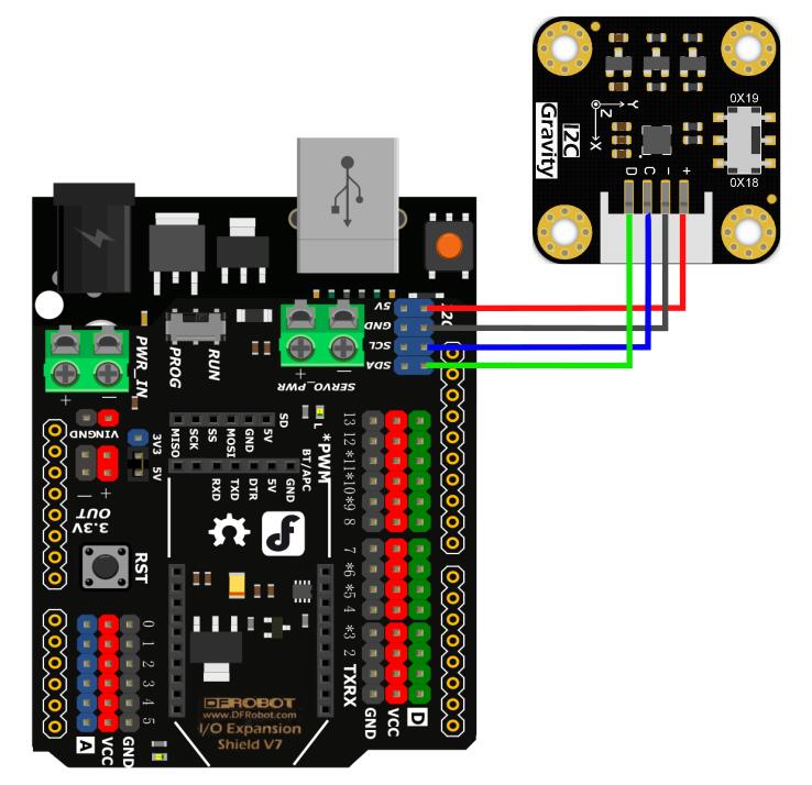
Wiring Diagram
Other Preparation Work
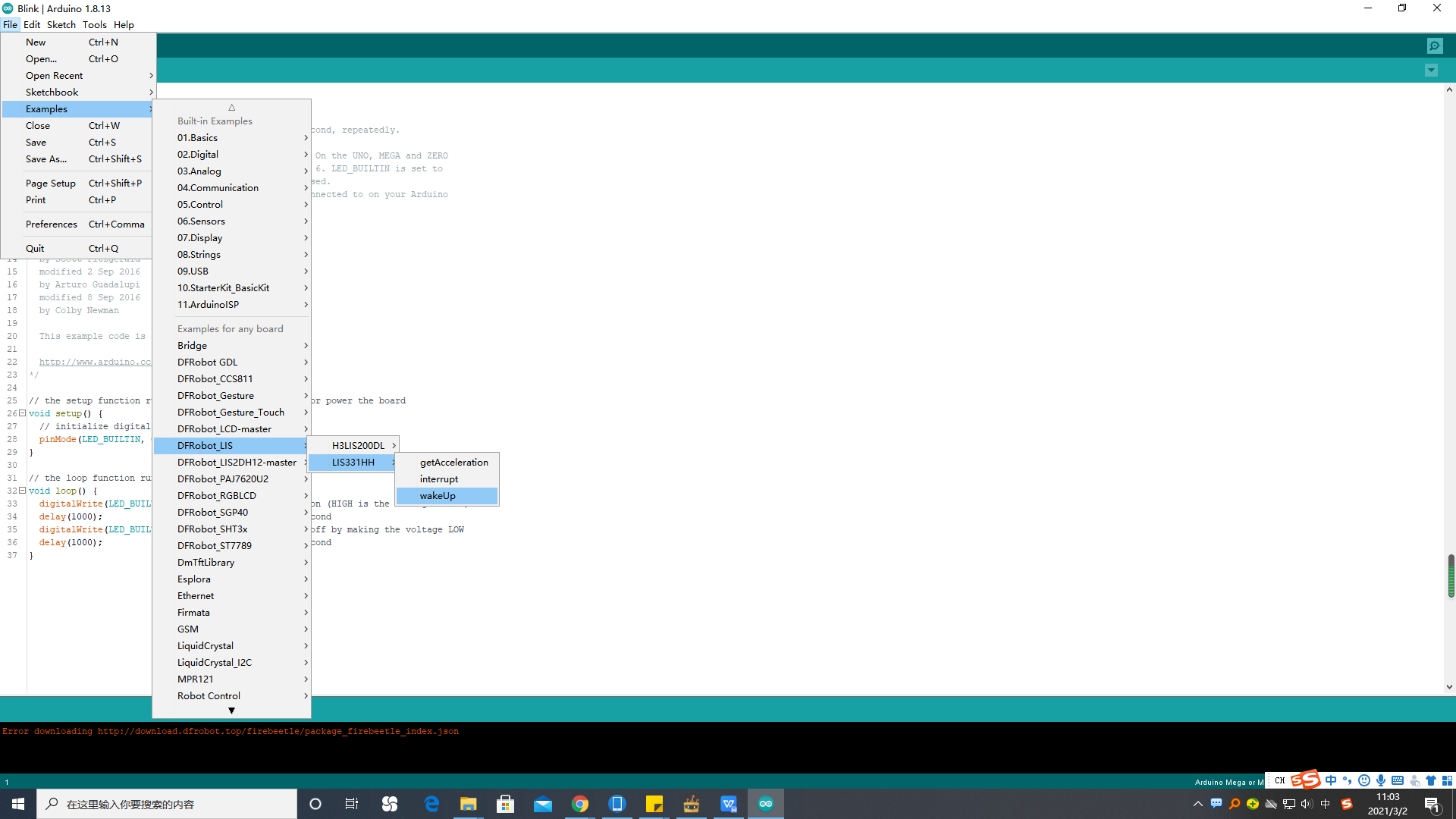
- Select wakeUp.ino from the library examples.
- Connect the int1/int2 pin of the module to the interrupt pin of the motherboard (e.g., UNO pin 2).
Sample Code
/**!
 * @file wakeUp.ino
 * @brief Use wake-up function
 * @n Phenomenon: To use this function, you need to turn the module into low-power mode first, and the measurement rate will be
 * @n very slow at this time. When an interrupt event set up before occurs, the module will enter normal mode, in which the measurement rate
 * @n will be accelerated to save power and provide sampling rate.
 * @n When using SPI, chip select pin can be modified by changing the value of macro LIS331HH_CS
 * @n This example needs to connect the int2/int1 pin of the module to the interrupt pin of the motherboard. Default UNO(2),
 * @n               Mega2560(2), Leonardo(3), microbit(P0),FireBeetle-ESP8266(D6),FireBeetle-ESP32((D6),FireBeetle-M0(6)
 * @copyright  Copyright (c) 2010 DFRobot Co.Ltd (http://www.dfrobot.com)
 * @licence     The MIT License (MIT)
 * @author [fengli]([email protected])
 * @version  V1.0
 * @date  2021-01-16
 * @get from https://www.dfrobot.com
 * @https://github.com/DFRobot/DFRobot_LIS
 */

#include <DFRobot_LIS.h>
//When using I2C communication, use the following program to construct an object by DFRobot_LIS331HH_I2C
/*!
 * @brief Constructor
 * @param pWire I2c controller
 * @param addr  I2C address(0x18/0x19)
 */
//DFRobot_LIS331HH_I2C acce(&Wire,0x18);
DFRobot_LIS331HH_I2C acce;

//When using SPI communication, use the following program to construct an object by DFRobot_LIS331HH_SPI
#if defined(ESP32) || defined(ESP8266)
#define LIS331HH_CS  D3
#elif defined(__AVR__) || defined(ARDUINO_SAM_ZERO)
#define LIS331HH_CS 3
#elif (defined NRF5)
#define LIS331HH_CS 2  //The pin on the development board with the corresponding silkscreen printed as P2
#endif
/*!
 * @brief Constructor
 * @param cs : Chip selection pinChip selection pin
 * @param spi :SPI controller
 */
//DFRobot_LIS331HH_SPI acce(/*cs = */LIS331HH_CS,&SPI);
//DFRobot_LIS331HH_SPI acce(/*cs = */LIS331HH_CS);

//Interrupt generation flag
volatile bool intFlag = false;
void interEvent(){
  intFlag = true;
  acce.setSleepFlag(false);
}
void setup(void){

  Serial.begin(9600);
  //Chip initialization
  while(!acce.begin()){
     delay(1000);
     Serial.println("Initialization failed, please check the connection or I2C address setting");
  }
    //Get chip id
  Serial.print("chip id : ");
  Serial.println(acce.getID(),HEX);

  /**
    set range:Range(g)
              eLis331hh_6g = 6,/<±6g>/
              eLis331hh_12g = 12,/<±12g>/
              eLis331hh_24g = 24/<±24g>/
  */
  acce.setRange(/*range = */DFRobot_LIS::eLis331hh_6g);

  /**
    Set data measurement rate:
      ePowerDown_0HZ = 0,
      eLowPower_halfHZ,
      eLowPower_1HZ,
      eLowPower_2HZ,
      eLowPower_5HZ,
      eLowPower_10HZ,
      eNormal_50HZ,
      eNormal_100HZ,
      eNormal_400HZ,
      eNormal_1000HZ,
  */
  // “sleep to wake-up”  need to put the chip in low power mode first
  acce.setAcquireRate(/*Rate = */DFRobot_LIS::eLowPower_halfHZ);

  /**
    Set the threshold of interrupt source 1 interrupt
    threshold:Threshold(g)
   */
  acce.setInt1Th(/*Threshold = */2);
  //Enable sleep wake function
  acce.enableSleep(true);

  /*!
    Enable interrupt
    Interrupt pin selection:
      eINT1 = 0,/<int1 >/
      eINT2,/<int2>/
    Interrupt event selection:
      eXLowThanTh,/<The acceleration in the x direction is less than the threshold>/
      eXHigherThanTh ,/<The acceleration in the x direction is greater than the threshold>/
      eYLowThanTh,/<The acceleration in the y direction is less than the threshold>/
      eYHigherThanTh,/<The acceleration in the y direction is greater than the threshold>/
      eZLowThanTh,/<The acceleration in the z direction is less than the threshold>/
      eZHigherThanTh,/<The acceleration in the z direction is greater than the threshold>/
   */
  acce.enableInterruptEvent(/*int pin*/DFRobot_LIS::eINT1,
                             /*interrupt = */DFRobot_LIS::eXHigherThanTh);
  #if defined(ESP32) || defined(ESP8266)
  //The D6 pin is used as the interrupt pin by default, and other non-conflicting pins can also be selected as the external interrupt pin.
  attachInterrupt(digitalPinToInterrupt(D6)/*Query the interrupt number of the D6 pin*/,interEvent,CHANGE);
  #elif defined(ARDUINO_SAM_ZERO)
  //The pin 5 is used as the interrupt pin by default, and other non-conflicting pins can also be selected as the external interrupt pin.
  attachInterrupt(digitalPinToInterrupt(5)/*Query the interrupt number of the pin 5*/,interEvent,CHANGE);
  #else
  /*    The Correspondence Table of AVR Series Arduino Interrupt Pins And Terminal Numbers
   * ---------------------------------------------------------------------------------------
   * |                                        |  DigitalPin  | 2  | 3  |                   |
   * |    Uno, Nano, Mini, other 328-based    |--------------------------------------------|
   * |                                        | Interrupt No | 0  | 1  |                   |
   * |-------------------------------------------------------------------------------------|
   * |                                        |    Pin       | 2  | 3  | 21 | 20 | 19 | 18 |
   * |               Mega2560                 |--------------------------------------------|
   * |                                        | Interrupt No | 0  | 1  | 2  | 3  | 4  | 5  |
   * |-------------------------------------------------------------------------------------|
   * |                                        |    Pin       | 3  | 2  | 0  | 1  | 7  |    |
   * |    Leonardo, other 32u4-based          |--------------------------------------------|
   * |                                        | Interrupt No | 0  | 1  | 2  | 3  | 4  |    |
   * |--------------------------------------------------------------------------------------
   */
  /*                      The Correspondence Table of micro:bit Interrupt Pins And Terminal Numbers
   * ---------------------------------------------------------------------------------------------------------------------------------------------
   * |             micro:bit                       | DigitalPin |P0-P20 can be used as an external interrupt                                     |
   * |  (When using as an external interrupt,      |---------------------------------------------------------------------------------------------|
   * |no need to set it to input mode with pinMode)|Interrupt No|Interrupt number is a pin digital value, such as P0 interrupt number 0, P1 is 1 |
   * |-------------------------------------------------------------------------------------------------------------------------------------------|
   */
  attachInterrupt(/*Interrupt No*/0,interEvent,CHANGE);//Enable the external interrupt 0, connect INT1/2 to the digital pin of the main control:
     //UNO(2), Mega2560(2), Leonardo(3), microbit(P0).
  #endif
}

void loop(void){
  //Get the acceleration in the three directions of xyz
  //The mearsurement range is ±6g, ±12g or ±24g, set by the setRange() function
  //If the chip is awakened, you can see a change in the frequency of data acquisition
  Serial.print("Acceleration x: ");
  Serial.print(acce.readAccX());
  Serial.print(" mg \ty: ");
  Serial.print(acce.readAccY());
  Serial.print(" mg \tz: ");
  Serial.print(acce.readAccZ());
  Serial.println(" mg");
  if(intFlag == true){
    /**
     Get whether the sensor is in sleep mode
     true(In sleep mode)/false(In normal mode)
     */
    Serial.println(acce.getSleepState()? "sleep mode": "normal mode");
    intFlag = 0;
  }
  delay(300);
}
Result
- When the interrupt event occurs, the serial monitor will print the acceleration data and the mode change (from sleep mode to normal mode).
Additional Information
- Screenshot of selecting the example code:
Was this article helpful?