Example Code for Arduino-Wakeup Function
Last revision 2025/12/17
This article provides a comprehensive guide to implementing the wake-up function in Arduino projects using the H3LIS200DL accelerometer and LIS Series Library, detailing hardware and software preparations, wiring configurations, and example code to enhance power management and dynamic data acquisition.
Hardware Preparation
- DFRduino UNO R3 (or similar) x 1
- H3LIS200DL Triple Axis Accelerometer (Breakout Version) x1
- Jumper wires
Software Preparation
- Arduino IDE
- Download and install the LIS Series Library and Sample Code. (About how to install the library?)
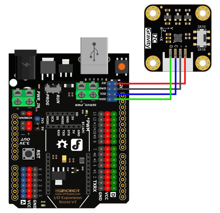
Wiring Diagram
Other Preparation Work
- Select wakeUp.ino from the library examples.
- Connect the interrupt pin (INT1) of the module to the interrupt pin of the Arduino (e.g., D6 for ESP32/ESP8266, pin 2 for UNO).
Sample Code
/**!
 * @file wakeUp.ino
 * @brief Use wake-up function
 * @n Phenomenon: To use this function, you need to turn the module into low-power mode first, and the measurement rate will be
 * @n very slow at this time. When an interrupt event set up before occurs, the module will enter normal mode, in which the measurement rate
 * @n will be accelerated to save power and provide sampling rate.
 * @n When using SPI, chip select pin can be modified by changing the value of macro H3LIS200DL_CS.
 * @copyright  Copyright (c) 2010 DFRobot Co.Ltd (http://www.dfrobot.com)
 * @licence     The MIT License (MIT)
 * @author [fengli]([email protected])
 * @version  V1.0
 * @date  2021-01-16
 * @get from https://www.dfrobot.com
 * @https://github.com/DFRobot/DFRobot_LIS
 */

#include <DFRobot_LIS.h>
//When using I2C communication, use the following program to construct an object by DFRobot_H3LIS200DL_I2C
/*!
 * @brief Constructor
 * @param pWire I2c controller
 * @param addr  I2C address(0x18/0x19)
 */
//DFRobot_H3LIS200DL_I2C acce(&Wire,0x18);
DFRobot_H3LIS200DL_I2C acce;

//When using SPI communication, use the following program to construct an object by DFRobot_H3LIS200DL_SPI
#if defined(ESP32) || defined(ESP8266)
#define H3LIS200DL_CS  D3
#elif defined(__AVR__) || defined(ARDUINO_SAM_ZERO)
#define H3LIS200DL_CS 3
#elif (defined NRF5)
#define H3LIS200DL_CS 2  //The pin on the development board with the corresponding silkscreen printed as P2
#endif
/*!
 * @brief Constructor
 * @param cs : Chip selection pinChip selection pin
 * @param spi :SPI controller
 */
//DFRobot_H3LIS200DL_SPI acce(/*cs = */H3LIS200DL_CS);

//Interrupt generation flag
volatile bool intFlag = false;

void interEvent(){
  intFlag = true;
}

void setup(void){

  Serial.begin(9600);
  //Chip initialization
  while(!acce.begin()){
     delay(1000);
     Serial.println("Initialization failed, please check the connection and I2C address settings");
  }
  //Get chip id
  Serial.print("chip id : ");
  Serial.println(acce.getID(),HEX);

  /**
    set range:Range(g)
              eH3lis200dl_100g,/< ±100g>/
              eH3lis200dl_200g,/< ±200g>/
  */
  acce.setRange(/*Range = */DFRobot_LIS::eH3lis200dl_100g);


  /**
   “sleep to wake-up”  need to put the chip in low power mode first
   Set data measurement rate:

      ePowerDown_0HZ = 0,
      eLowPower_halfHZ,
      eLowPower_1HZ,
      eLowPower_2HZ,
      eLowPower_5HZ,
      eLowPower_10HZ,
      eNormal_50HZ,
      eNormal_100HZ,
      eNormal_400HZ,
      eNormal_1000HZ,
  */
  acce.setAcquireRate(/*Rate = */DFRobot_LIS::eLowPower_halfHZ);

  /**
    Set the threshold of interrupt source 1 interrupt
    threshold:Threshold(g)
   */
  acce.setInt1Th(/*Threshold = */6);
  //Enable sleep wake function
  acce.enableSleep(true);
  Serial.println("sleep");
  /*!
    Enable interrupt
    Interrupt pin selection:
      eINT1 = 0,/<int1 >/
      eINT2,/<int2>/
    Interrupt event selection:
      eXLowerThanTh ,/<The acceleration in the x direction is less than the threshold>/
      eXHigherThanTh ,/<The acceleration in the x direction is greater than the threshold>/
      eYLowerThanTh,/<The acceleration in the y direction is less than the threshold>/
      eYHigherThanTh,/<The acceleration in the y direction is greater than the threshold>/
      eZLowerThanTh,/<The acceleration in the z direction is less than the threshold>/
      eZHigherThanTh,/<The acceleration in the z direction is greater than the threshold>/
   */
  acce.enableInterruptEvent(/*int pin*/DFRobot_LIS::eINT1,/*interrupt event = */DFRobot_LIS::eZHigherThanTh);

  #if defined(ESP32) || defined(ESP8266)||defined(ARDUINO_SAM_ZERO)
  attachInterrupt(digitalPinToInterrupt(D6)/*Query the interrupt number of the D6 pin*/,interEvent,CHANGE);
  #else
  /*    The Correspondence Table of AVR Series Arduino Interrupt Pins And Terminal Numbers
   * ---------------------------------------------------------------------------------------
   * |                                        |  DigitalPin  | 2  | 3  |                   |
   * |    Uno, Nano, Mini, other 328-based    |--------------------------------------------|
   * |                                        | Interrupt No | 0  | 1  |                   |
   * |-------------------------------------------------------------------------------------|
   * |                                        |    Pin       | 2  | 3  | 21 | 20 | 19 | 18 |
   * |               Mega2560                 |--------------------------------------------|
   * |                                        | Interrupt No | 0  | 1  | 2  | 3  | 4  | 5  |
   * |-------------------------------------------------------------------------------------|
   * |                                        |    Pin       | 3  | 2  | 0  | 1  | 7  |    |
   * |    Leonardo, other 32u4-based          |--------------------------------------------|
   * |                                        | Interrupt No | 0  | 1  | 2  | 3  | 4  |    |
   * |--------------------------------------------------------------------------------------
   */
  /*                      The Correspondence Table of micro:bit Interrupt Pins And Terminal Numbers
   * ---------------------------------------------------------------------------------------------------------------------------------------------
   * |             micro:bit                       | DigitalPin |P0-P20 can be used as an external interrupt                                     |
   * |  (When using as an external interrupt,      |---------------------------------------------------------------------------------------------|
   * |no need to set it to input mode with pinMode)|Interrupt No|Interrupt number is a pin digital value, such as P0 interrupt number 0, P1 is 1 |
   * |-------------------------------------------------------------------------------------------------------------------------------------------|
   */
  attachInterrupt(/*Interrupt No*/0,interEvent,CHANGE);//Enable the external interrupt 0, connect INT1/2 to the digital pin of the main control:
     //UNO(2), Mega2560(2), Leonardo(3), microbit(P0).
  #endif
  delay(1000);
}

void loop(void){
  //Get the acceleration in the three directions of xyz
  //The mearsurement range is ±100g or ±200g, set by setRange() function.
  Serial.print("Acceleration x: ");
  Serial.print(acce.readAccX());
  Serial.print(" g \ty: ");
  Serial.print(acce.readAccY());
  Serial.print(" g \tz: ");
  Serial.print(acce.readAccZ());
  Serial.println(" g");
  delay(300);
  if(intFlag == 1){
    Serial.println("wake up");
    intFlag = 0;
  }
}
Result
When the acceleration in the Z direction exceeds 6g, the module wakes up from low-power mode, and "wake up" is printed on the serial monitor.
- Screenshot of the code selection:

Was this article helpful?