Usage Example for Arduino-ESP32-Digital/Analog Sensor Data Acquisition
The article serves as a detailed guide for utilizing Arduino ESP32 to acquire sensor data, focusing on the configuration of BLE Sensor Beacon and LM35 Temperature Sensor. It encompasses hardware and software preparation, wiring diagrams, and configuration steps for accurate data acquisition and processing, making it an essential resource for enhancing sensor-based projects.
Hardware Preparation
- Fermion: BLE Sensor Beacon ×1
- Rainbow link or any other 3.3V USB-TTL convertor ×1
- Gravity: Analog LM35 Temperature Sensor ×1
- FireBeetle 2 ESP32-E or any other ESP32 board ×1
- Dupond cable ×1
Software Preparation
- Mobile App: NanoBeacon BLE Scanner (iOS/Android)
- Config Tool: NanoBeaconConfigTool_V3.2.11
- IDE: Arduino IDE with FireBeetle ESP32-E Setup
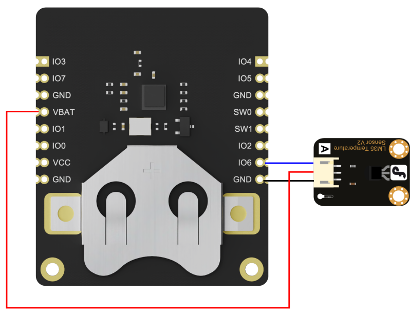
Wiring Diagram
Configure Sensor Beacon
*Note: The module can only be burned once, do not click "Burn/Program" directly to burn before confirming the configuration information. You can test the module by "Run inRAM", and "Run in RAM" can be used for unlimited times before burning, and the system will be reset after power failure.
The input voltage of the module's ADC interface must not exceed 1.6V. If the voltage of the accessed sensors may exceed 1.6V, the sensors need to be connected to GPIO6, which adds 2.06 times the divider resistor to support an input voltage of up to 3.3V.
-
1.DownloadNanoBeaconConfigTool_V3.2.11,Run NanoBeaconConfig.exe
-
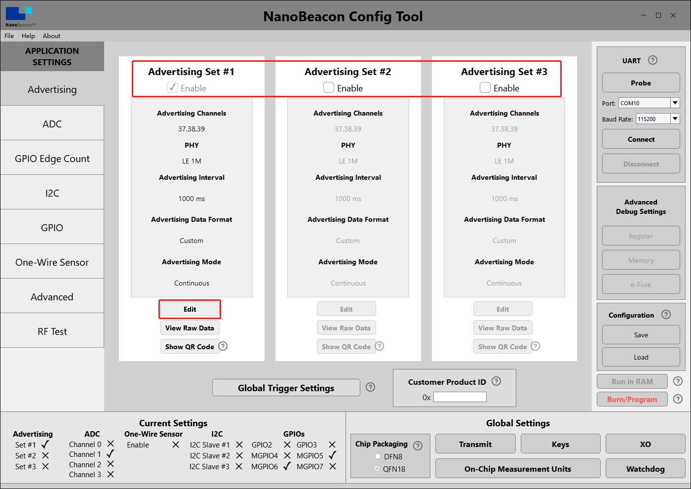
2.Advertising
Fermion: BLE Sensor beacons can be set to three broadcast channels, check Enable to open the corresponding broadcast channel, the default is to open one, Edit to enter the configuration page.
-
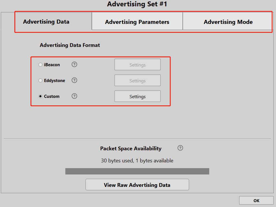
3.Advertising Set#1 - Edit - Avdertising Data
Three data formats can be set: iBeacon, Eddystone and Custom. In the tutorial, we will mainly use Custom.
-
4.Advertising Set#1 - Edit - Avdertising Data - Custom Settings
Tick "Device Name", enter "Fermion: Sensor Beacon", the name can be any one, mobile phones and ESP32 scanning can be directly based on the name of the filter.
Tick "Manufacturer Specific Data", click "EDIT" to configure the data.

-
5.Advertising Set#1 - Edit - Avdertising Data - Custom Settings - EDIT
Here only configure an analogue data, drop-down box select "ADC CH1", check: "Big Endian", click "Append to Data", you can see in the window "0x<ADC CH1 2byte 1 0>", click OK to exit!

-
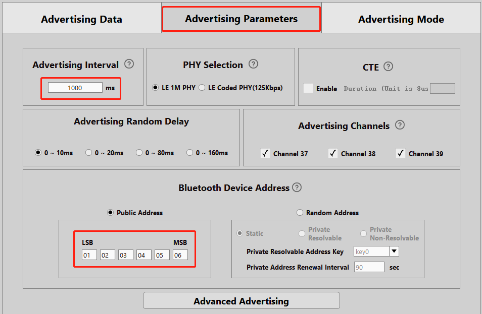
6.Advertising Set#1 - Edit - Avdertising Parameters
Here to set the broadcast interval and address, according to the need to modify can be completed after the completion of the OK exit, so that the broadcast data format configuration is complete, the module will be 1S / time broadcast data
-
7.ADC
Next, do the ADC related configuration, Fermion: BLE sensor beacons use IO6 for analogue acquisition, so Enable "ADC Channel 2 MPGIO 6" in the ADC screen and click on Edit to configure it

-
8.ADC - ADC Channel 1 MPGIO 6 - Edit
A review of the IN100 datasheet shows that the IN100 chip used in the Fermion: BLE Sensor Beacon can only receive a maximum of 1.6V at the ADC.
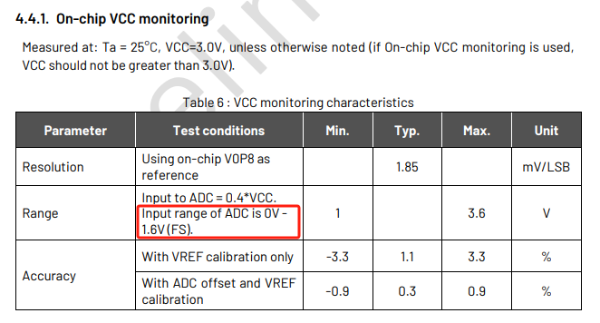
Since the output voltage of many analogue sensors will reach his supply voltage (often 3.3V). So we put a resistor in series with GPIO6 to do the voltage divider 2.06.
Here we will modify the relevant configuration in the ADC settingsModifying the Unit to 0.001 is easy to calculate and has little effect on the accuracy, but can be left unchanged if there is a very high demand for accuracy. Next, we need to remap the voltage value after voltage division.
Value of 1.4V Revised to 2.898
Value of 0.4V Revised to 0.828
At this point, the ADC acquisition related configuration is completed, at this time the beacon broadcast data will be "sensor signal input" voltage value, unit mv

-
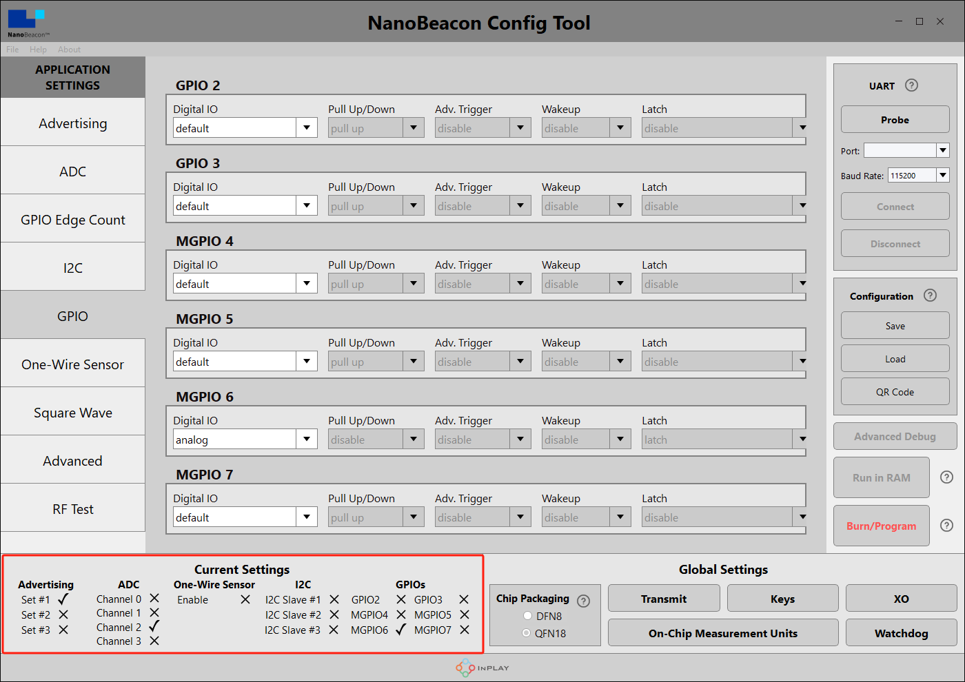
9.GPIO
Since MGPIO 6 is used as an ADC input, it needs to be configured as "analog".

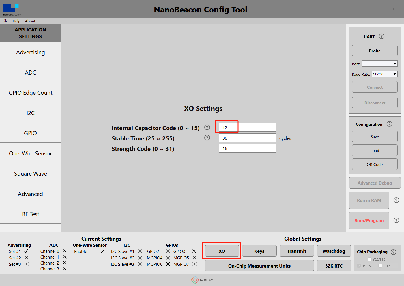
- 10.Crystal Capacitance Matching
The NanoBeaconConfig Tool can be set to match the crystal capacitance, and in conjunction with our circuit, in order to keep the frequency bias at an optimal level, we recommend that you change the following two parameters to 12.

-
11.Check Configuration
In the lower left corner of the software, you can see that we have enabled Set #1, ADC Channel 2 and MGPIO6.
-
12.Hardware connection
Hardware connections according to the wiring diagram
-
13.Connecting the module to the PC
In the upper right corner of the software, click "Probe" to refresh the port, after refreshing, select the corresponding port, click "Connect", there will be a pop-up window after successful connection.

-
14.Run test
Click on "Run in RAM" and a pop-up will appear when it's done.
*Note: The module can only be burned once, do not click "Burn/Program" directly to burn before confirming the configuration information. You can test the module by "Run in RAM", and "Run in RAM" can be used for unlimited times before you click "Burn".But before your second "Run in RAM" test the Beacon will need to be completely power off(Both VCC and cell coin battery) .Otherwise, the Beacon could not be connected.

Mobile app to get data
-
1.Take an IOS device for example, AppStore install and open InPlay
-
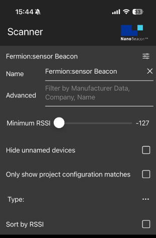
2.If there are too many other beacons in the neighbourhood to find our device, we can enter the device name of the beacon in the filter, in the tutorial for configuring sensor beacons step 4, we named the Device Name "Fermion: Sensor Beacon".
-
3.You can see that only "Fermion: Sensor Beacon" remains in the menu, click on it to see the details.
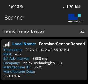 -
4.Data interpretation
"Fermion: Sensor Beacon" is the Device Name set in step 4 of the Sensor Beacon configuration.
"06:05:04:03:02:01" is the address set in step 6 of configuring sensor beacons
In "05050114", 0505 is the manufacturer's number and 0114 is the ADC acquisition data set in step 5 of configuring the sensor beacon
-
5.Sensor Data Calculation
  Currently known beacon collected sensor data for "0X0114", will be converted to decimal 276, that is, the beacon collected the voltage value of 276mv

  The sensor we connected is LM35, by checking the [Datasheet of LM35](https://image.dfrobot.com/image/data/DFR0023/DFR0023_Datasheet.pdf "Datasheet of LM35"), we know that the correspondence between LM35 output voltage and temperature is 10mV/℃, that is, the data of LM35 temperature sensor broadcasted by the beacon is 27.6℃.
4. ESP32 Get Data
-
Prepare the Arduino IDE&ESP32set up:FireBeetle_ESP32_E Set up
-
Upload the following programme for the ESP32
/*
   Based on Neil Kolban example for IDF: https://github.com/nkolban/esp32-snippets/blob/master/cpp_utils/tests/BLE%20Tests/SampleScan.cpp
   Ported to Arduino ESP32 by Evandro Copercini
   Changed to a beacon scanner to report iBeacon, EddystoneURL and EddystoneTLM beacons by beegee-tokyo
*/

#include <Arduino.h>
#include <BLEDevice.h>
#include <BLEUtils.h>
#include <BLEScan.h>
#include <BLEAdvertisedDevice.h>
#include <BLEEddystoneURL.h>
#include <BLEEddystoneTLM.h>
#include <BLEBeacon.h>
#define ENDIAN_CHANGE_U16(x) ((((x)&0xFF00) >> 8) + (((x)&0xFF) << 8))

float Sensor_Data;
int scanTime = 5; //In seconds
BLEScan *pBLEScan;

class MyAdvertisedDeviceCallbacks : public BLEAdvertisedDeviceCallbacks
{
    void onResult(BLEAdvertisedDevice advertisedDevice)
    {
      if (advertisedDevice.haveName())
      {
        if(String(advertisedDevice.getName().c_str()) == "Fermion:Sensor Beacon"){
          Serial.print("Device name: ");
          Serial.println(advertisedDevice.getName().c_str());
          std::string strManufacturerData = advertisedDevice.getManufacturerData();
          uint8_t cManufacturerData[100];
          strManufacturerData.copy((char *)cManufacturerData, strManufacturerData.length(), 0);
          Serial.printf("strManufacturerData: %d ", strManufacturerData.length());
            for (int i = 0; i < strManufacturerData.length(); i++)
            {
              Serial.printf("[%X]", cManufacturerData[i]);
            }
            Sensor_Data = int(cManufacturerData[2]<<8 | cManufacturerData[3]);
            Serial.println();
            Serial.print("Voltage:");Serial.print(int(Sensor_Data));Serial.println("mV");
            Serial.print("Temp_LM35:");Serial.print(Sensor_Data/10);Serial.println("℃");
            Serial.println("------------------");
        }
      }
    }
};
void setup()
{
  Serial.begin(115200);
  Serial.println("Scanning...");

  BLEDevice::init("");
  pBLEScan = BLEDevice::getScan(); //create new scan
  pBLEScan->setAdvertisedDeviceCallbacks(new MyAdvertisedDeviceCallbacks());
  pBLEScan->setActiveScan(true); //active scan uses more power, but get results faster
  pBLEScan->setInterval(100);
  pBLEScan->setWindow(99); // less or equal setInterval value
}
void loop()
{
  // put your main code here, to run repeatedly:
  BLEScanResults foundDevices = pBLEScan->start(scanTime, false);
  pBLEScan->clearResults(); // delete results fromBLEScan buffer to release memory
  delay(2000);
}

-
This programme is modified from the BLE_Beacon_Scanner that comes with the ESP32, and can be modified as needed.

Confirm the data and burn into Beacon
-
*Note: The module can only be burned once, if you only want to test the function, you can skip this step.
-
The above data format is broadcast in a customised format, intended to enable you to use it quickly, please refer to the software specification to configure yourself according to your needs for other formats.
-
After confirming that the data is correct, the data format can be burned and cured into the chip.
-
Click the "Burn/Program" button in the lower right corner to burn the program, and there will be a pop-up window prompting the success of burning.
Was this article helpful?