Usage Example for Arduino-ESP32-I2C Sensor Data Acquisition
Acquire temperature and humidity data from a Fermion: SHT40 I2C sensor using the Fermion BLE Sensor Beacon, then read and display the data via an ESP32 or mobile app. Users will learn how to configure the beacon for I2C sensors and parse BLE broadcast data.
*Note: If the module is bricked after burning due to configuration file error, the user will be responsible for it. The module can only be burned once, please don't click "Burn/Program" to burn the module before confirming the configuration information, I2C sensors don't support "Run in RAM" test and can only be burned directly, it is recommended to use the Sensor Sample Configuration File provided by DFRobot. To use I2C sensors for which no profile is provided, please consult the tutorials in the Wiki.
Hardware Preparation
- Fermion: BLE Sensor Beacon ×1
- Rainbow link or any other 3.3V USB-TTL convertor ×1
- Fermion: SHT40 Temperature & Humidity Sensor ×1
- Windows/Linux/Mac OS computer ×1
- FireBeetle 2 ESP32-E ×1
- CR2032 battery ×1
- Dupond wire
Software Preparation
- Mobile App: NanoBeacon BLE Scanner
- Config Tool: NanoBeaconConfigTool
- IDE: Arduino IDE with FireBeetle ESP32-E Setup
- Sample Files: DFRobot_FermionBLE GitHub Repo
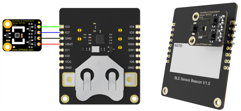
Wiring Diagram
Configuration of sensor beacon
-
1.Download NanoBeaconConfigTool,Run NanoBeaconConfig.exe
-
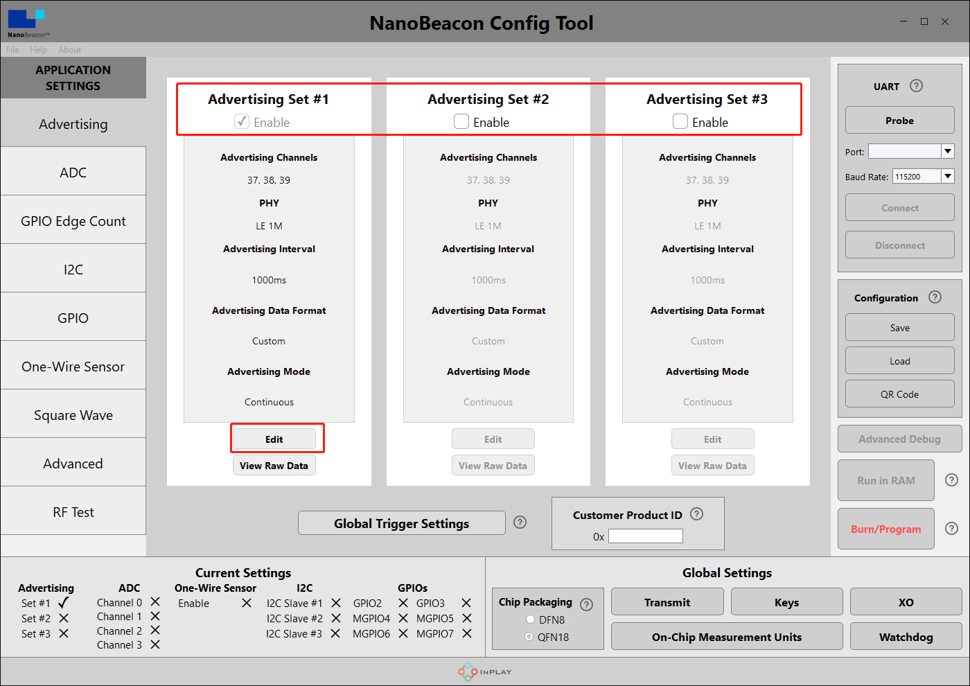
2.Advertising
Fermion: BLE Sensor beacons can be set to three broadcast channels, check Enable to open the corresponding broadcast channel, the default is to open one, Edit to enter the configuration page.
-
3.Advertising Set#1 - Edit - Avdertising Data
Three data formats can be set: iBeacon, Eddystone and Custom. In the tutorial, we will mainly use Custom.

-
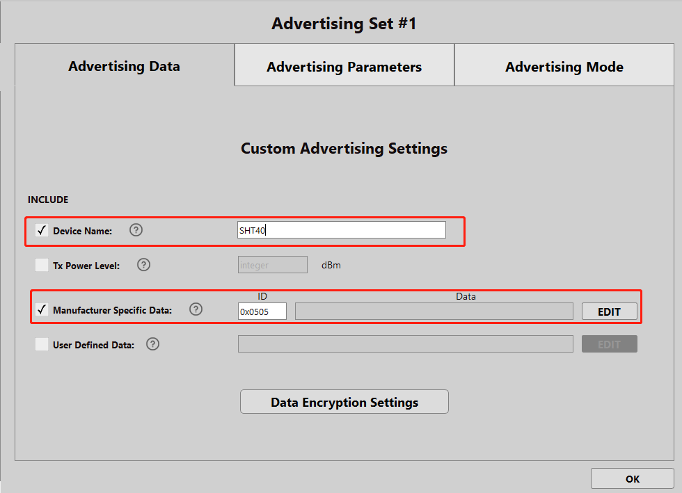
4.Advertising Set#1 - Edit - Avdertising Data - Custom Settings
Tick "Device Name", enter "SHT40", the name can be arbitrary, it is recommended that the length of 5 characters or less, the name is too long will occupy the data bits, mobile phones and ESP32 scanning can be directly based on the name of the screening
Tick "Manufacturer Specific Data" and click "EDIT" to configure the data.
-
5.Advertising Set#1 - Edit - Avdertising Data - Custom Settings - EDIT
Only one I2C data is configured here, select "I2C Slave #1 Read Data" in the drop-down box.
If you are using an I2C sensor that returns six or more bytes of I2C data frames in a single pass. You need to match Offset and byte for byte selection and rounding.
"Offset" Explanation:
Set the byte bias of the sensor I2C feedback, since the I2C feedback is a string of bytes. Sometimes the first few bytes of sensor feedback can be discarded to save the on-board IN100 data buffer.
If the sensor feedback: 00 00 06 FF, at this time the first two bytes do not have any significance, you can set Offset to 2 and discard the first two bytes.
"Bytes" Explanation:
Since the built-in IN100 chip's buffer uses a ring queue for data acquisition, while the buffer stores a maximum of 5 bytes at the same time. Therefore, the number of bytes read into the buffer is limited to 5 at a time.
Then, click Append to Data at the top to see "0x<I2C1R0 5byte 0 0>" in the window, click OK to exit.

-
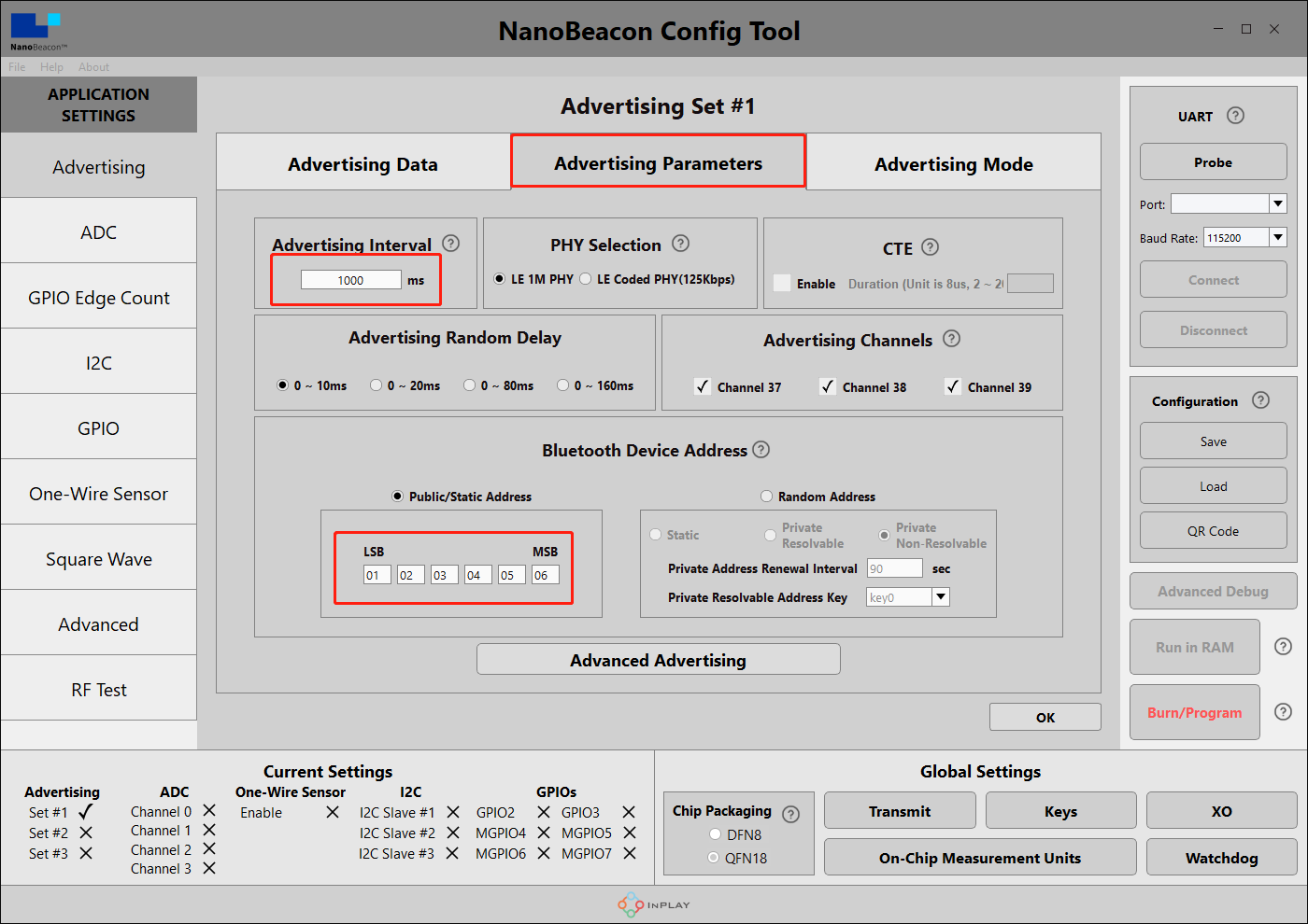
6.Advertising Set#1 - Edit - Avdertising Parameters
Here set the broadcast interval and address, modify as needed, OK to exit when finished. Here the broadcast interval is set to 1000ms, that is, the module will broadcast data at 1S/time.
Advertising Interval is the time interval of auto broadcast.
Bluetooth Device address can set the address of Fermion: BLE sensor beacon. (LSB is the least significant bit, MSB is the most significant bit)
-
7.Communication setup ---- pre-testing with Arduino
Since the I2C configuration of the Fermion: BLE Sensor Beacon can only be burned once, it is recommended to first test the I2C communication control in a controller such as an Arduino for correctness using code programming.
Use the Arduino UNO to upload I2C to read the code and confirm that the sensor is working correctly
Wire diagram can refer to SHT40(SEN0428)wiki
Code is as followed:
#include <Wire.h>

#define SHT40_ADDRESS 0x44 // I2C address of the sensor, here 0x44 for SHT40
int l = 5;// Read Byte Length

void setup(){
  Serial.begin(115200);
  Wire.begin();
}

void loop() {

  Wire.beginTransmission(SHT40_ADDRESS);
  Wire.write(0xFD);//i2ctx:3
  Wire.endTransmission();//i2c null

  delay(10); // The programme waits 10ms for the SHT40 to get ready

  Wire.requestFrom(SHT40_ADDRESS, 6);
  if (Wire.available() >= l) {
    byte data[l];
    for (int i = 0; i < l; i++) {//Read the data output from the I2C sensor
      data[i] = Wire.read();
      Serial.print(data[i], HEX);
      Serial.print(" ");
    }
  Serial.println();
  }
  Wire.endTransmission();//i2c null
  delay(1000);
}
When a value appears in the serial monitor, it means that the SHT40 sensor is outputting normally and you can continue with the following configuration.
Code Explanation:
In common I2C communication sensors, the communication flow tends to be:
Step 1, The master writes a read command to the I2C of the sensor ——>the master reads data to the sensor
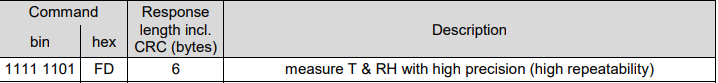
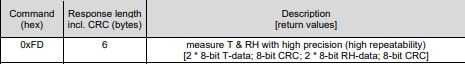
It is the master control that writes 0xFD byte to the SHT40 sensor. Checking the datasheet shows that the 0xFD byte is an instruction for the SHT40 sensor to measure temperature and humidity.
Step 2, the master waits for some time while the sensor prepares the data
delay(10);
Indicates that the master waits for 10ms, check the datasheet to find out:
SHT40 recommends a minimum wait time of 1ms, but here we usually set the wait time to 10ms to be on the safe side.

Step three, the master requests data from the sensor
Wire.requestFrom(SHT40_ADDRESS, 6);
It is the master requesting the SHT40 to read 6 bytes, checking the datasheet shows that this frame data:
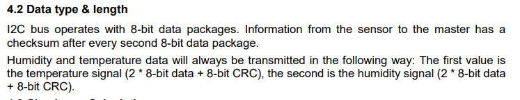
The 1st and 2nd bytes are temperature data, and the 3rd bit is CRC check.
The 4th and 5th bytes are humidity data, and the 6th bit is CRC checksum.
- 8.I2C Communication Settings —— I2C Parameter Configuration
Next, I2C-related configuration is performed to enable the Fermion: BLE Sensor Beacon to acquire I2C sensor data.
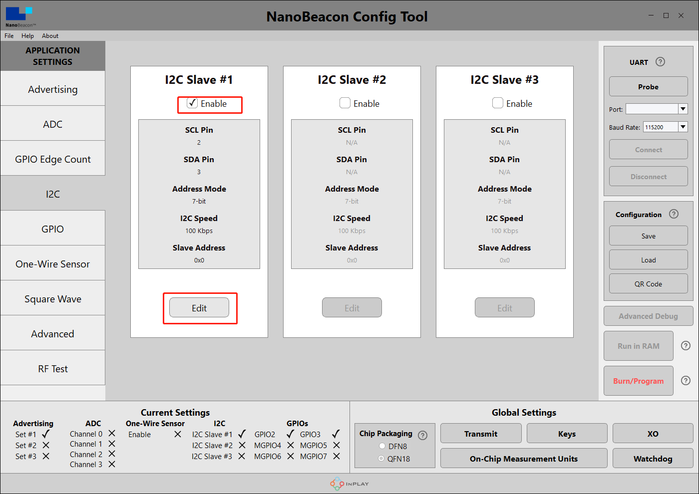
Once we are back in the Nano Beacon Config Tool and have selected the I2C tab on the left.
There are three channels for I2C data acquisition, here we select channel 1 for I2C sensor configuration. Enable "I2C Slave#1" in the I2C interface and click Edit to configure.
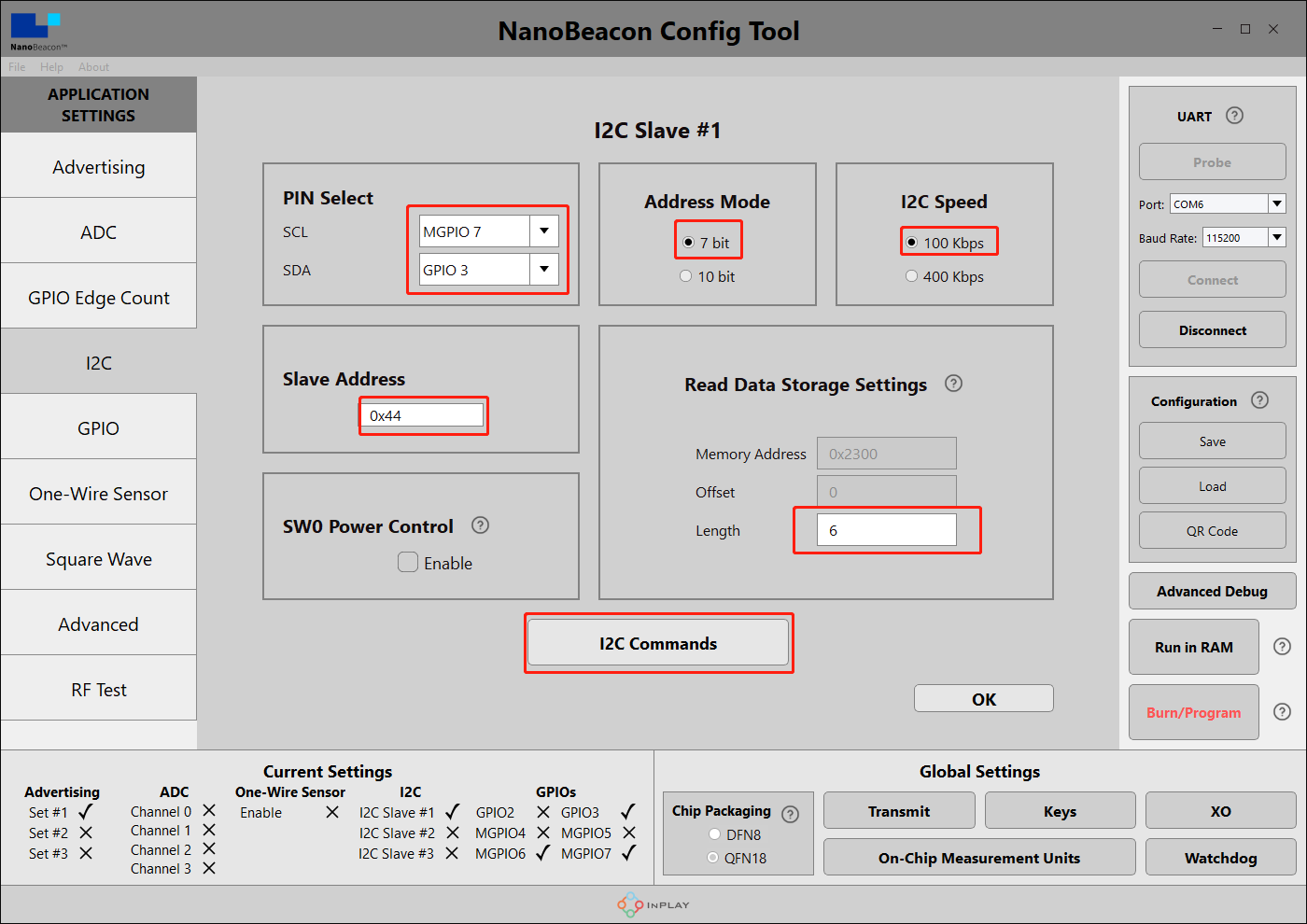
According to the pin layout of the module, select SCL as MGPIO7 and SDA as GPIO3 in PIN Select. the connection between the BLE beacon and SHT40 will be more reasonable as shown in the figure below after this layout.
Slave Address is 0x44(SHT40 I2C Address)
Address Mode is 7 bit(I2C standard mode)
I2C Speed 为100kps(I2C standard speed)
Read Data Storage Settings set Length to 5. Here is the ring buffer mechanism, when read data length > Length, it will wrap back automatically. By looking at the SHT40 datasheet it can be seen that when the master sends the command 0xFD, the sensor will return: [2 * 8-bit T-data; 8-bit CRC; 2 * 8-bit RH-data; 8-bit CRC], a total of 6 bytes.
However, due to the buffer settings of the beacon's on-board chip, Fermion: Sensor beacons can only receive a maximum of 5 consecutive bytes after sending 1 command,Combined with the data returned by SHT40, the last bit is the humidity check bit, which can be discarded, so the data obtained from SHT40 has a total of 5 bits, so Read Data Storage Settings sets Length to 5.
- 9.I2CCommunication Settings —— I2C Parameter Configuration
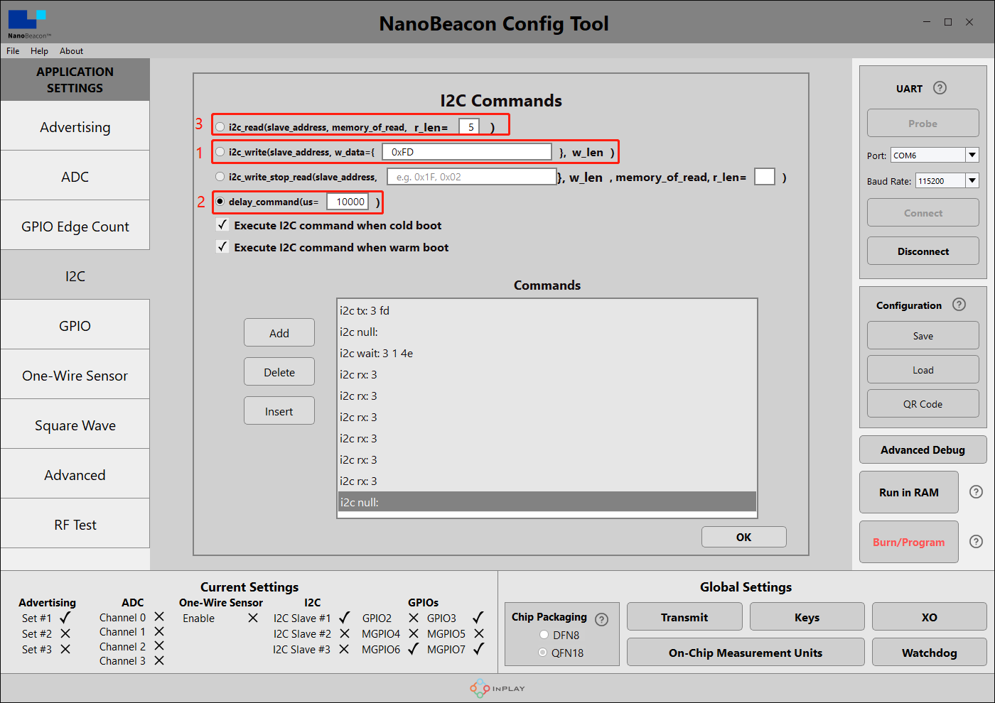
Click I2C Commands to set commands.
According to the I2C communication instructions in step 7, we first need to have the sensor beacon send the read command (0xFD) to the SHT40 chip:
Tick Execute I2C command when cold boot as well as Execute I2C command when warm boot to select the line for i2c_write, fill in the command 0xFD that will read the SHT40 sensor, and then click Add to add it to the command list.
Next, we need a 10ms delay to wait for the SHT40 to prepare the data:
We wait 10ms to select the line for delay_command, fill in the delay of 10000us, and click Add to add to the list of commands.
Finally, we need to read the temperature and humidity data from the SHT40:
Select the line of i2c_read, fill in the length of data to be read as 5 (IN100 reads up to 5 bytes at a time), and then click Add to add to the command list.
When the configuration is complete, the format should be consistent with the figure below.
The above SHT40 samples can be downloaded and loaded directly:Fermion: BLE Beacon
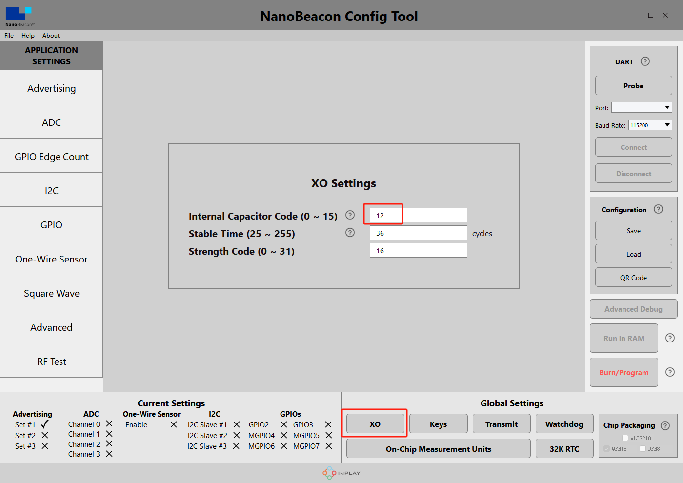
- 10.Crystal Capacitance Matching
The NanoBeaconConfig Tool can be set to match the crystal capacitance, and in conjunction with our circuit, in order to keep the frequency bias at an optimal level, we recommend that you change the following two parameters to 12.

-
11.Check Configuration
In the bottom left corner of the software you can see that we have enabled Set #1, I2C Slave #1, GPIO3 and MGPIO7.

-
12.Connecting modules to PC ---- hardware
Hardware connections according to the wiring diagram
-
13.Connecting modules to PC ---- software
In the upper right corner of the software, click "Probe" to refresh the port, after refreshing, select the corresponding port, click "Connect", there will be a pop-up window after successful connection.

-
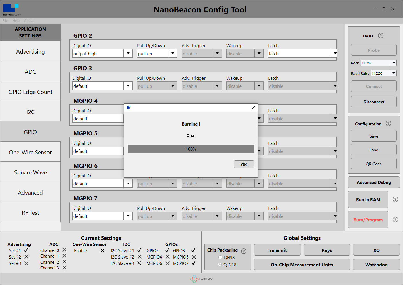
14.Burn Configuration
Click on "Burn/Program" and there will be a pop-up when it's done.
*Note: The module can only be burned once in I2C configuration, please check in detail whether the commands in the above process are correct before burning.!!!
Mobile app to get data
-
1.Take an IOS device for example, AppStore install and open InPlay
-
2.If there are too many other beacons in the neighbourhood to find our device, you can enter the device name of the beacon in the filter. In the tutorial for configuring sensor beacons in step 4, we named the Device Name "SHT40".


-
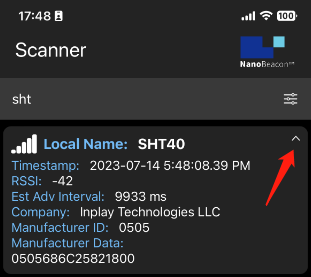
3.You can see that only "SHT40" remains in the menu, click on it to see the details.

-
4.Data interpretation
"SHT40" is the Device Name set in step 4 of the sensor beacon configuration.
"686C25 821800" is the I2C acquisition data set in step 5 of Configuring Sensor Beacons
-
5.Sensor Data Calculation
The current known sensor data captured by the beacon is "686C25 821800", which is 0x68 0x6C 0x25 0x82 0x18 0x00.
By querying the SHT40 datasheet, it is clear that when 0xFD is written to the sensor, the sensor will reply 6 bytes of data to the I2C host:
Since IN100 can only receive 5 bytes of data in one tx instruction, but the SHT40 will spit out 6 bars of data when it receives 0xFD, the sixth bit of data can't be read, i.e., it is the default value of 0x00.
Take, for example, our reading of 686C25 821800, viz:
Temperature value two bytes are: 0x68,0x6C, the original value is 0x686C = 26732
Temperature value CRC checksum is: 0x25
Humidity value two bytes are: 0x82,0x18, the original value is 0x8218 = 33304
Humidity data CRC cannot be read due to hardware limitations.Then go through the calculation formula in the SHT40 datasheet:
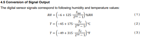
Can be derived:
Temperature = -45 + (175x26732/65535) ≈ 26.38°C
Humidity = -6 + (125x33304/65535) ≈ 57.52 per centESP32 acquiring data
-
Prepare the Arduino IDE & Done ESP32 setup:FireBeetle_ESP32_E Set up tutorial
-
Upload the following program for ESP32
/*
Based on Neil Kolban example for IDF: https://github.com/nkolban/esp32-snippets/blob/master/cpp_utils/tests/BLE%20Tests/SampleScan.cpp
Ported to Arduino ESP32 by Evandro Copercini
Changed to a beacon scanner to report iBeacon, EddystoneURL and EddystoneTLM beacons by beegee-tokyo
*/
#include <Arduino.h>
#include <BLEDevice.h>
#include <BLEUtils.h>
#include <BLEScan.h>
#include <BLEAdvertisedDevice.h>
#include <BLEEddystoneURL.h>
#include <BLEEddystoneTLM.h>
#include <BLEBeacon.h>
#define ENDIAN_CHANGE_U16(x) ((((x)&0xFF00) >> 8) + (((x)&0xFF) << 8))
float TemperatureData,HumidityData;
float Temperature,Humidity;
//Setting up ESP32 to scan for Bluetooth devices once every 5 seconds
int scanTime = 5; //In seconds
BLEScan *pBLEScan;
class MyAdvertisedDeviceCallbacks : public BLEAdvertisedDeviceCallbacks
{
void onResult(BLEAdvertisedDevice advertisedDevice)
{
if (advertisedDevice.haveName())
{
if(String(advertisedDevice.getName().c_str()) == "SHT40")//Scan for a Bluetooth device named SHT40
{
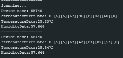
Serial.print("Device name: ");
Serial.println(advertisedDevice.getName().c_str());
std::string strManufacturerData = advertisedDevice.getManufacturerData();
uint8_t cManufacturerData[100];
strManufacturerData.copy((char *)cManufacturerData, strManufacturerData.length(), 0);
Serial.printf("strManufacturerData: %d ", strManufacturerData.length());
for (int i = 0; i < strManufacturerData.length(); i++)
{
Serial.printf("[%X]", cManufacturerData[i]);
}
//Getting raw data from SHT40
TemperatureData = int(cManufacturerData[2]<<8 | cManufacturerData[3]);
HumidityData = int(cManufacturerData[5]<<8 | cManufacturerData[6]);
//Convert raw data into temperature and humidity data
Temperature = (175 * TemperatureData/65535) - 45;
Humidity = (125 * HumidityData/65535) - 6;
Serial.println();
Serial.print("TemperatureData:");Serial.print(Temperature);Serial.println("℃");
Serial.print("HumidityData:");Serial.print(Humidity);Serial.println("%");
Serial.println("------------------");
}
}
}
};
void setup()
{
Serial.begin(115200);
Serial.println("Scanning...");
BLEDevice::init("");
pBLEScan = BLEDevice::getScan(); //create new scan
pBLEScan->setAdvertisedDeviceCallbacks(new MyAdvertisedDeviceCallbacks());
pBLEScan->setActiveScan(true); //active scan uses more power, but get results faster
pBLEScan->setInterval(100);
pBLEScan->setWindow(99); // less or equal setInterval value
}
void loop()
{
// put your main code here, to run repeatedly:
BLEScanResults foundDevices = pBLEScan->start(scanTime, false);
pBLEScan->clearResults(); // delete results fromBLEScan buffer to release memory
delay(2000);
}
- This programme is modified from the BLE_Beacon_Scanner that comes with the ESP32, and can be modified as needed.
Was this article helpful?