Hardware Control
This guide introduces basic hardware control on Jetson, including GPIO operations with the Jetson.GPIO library and I2C device debugging with i2c-tools.
Jetson TX1, TX2, AGX Xavier, and Nano development boards include a 40-pin GPIO header, similar to the 40-pin header in the Raspberry Pi.
GPIO
-
The digital input and output of these GPIOs can be controlled using the Python library provided in the Jetson GPIO library package.
-
The Jetson GPIO library provides all the public APIs provided by the RPi.GPIO library. The use of each API is discussed below:
-
To import the Jetson.GPIO module, use:
import Jetson.GPIO as GPIO -
Pin Numbering
-
The Jetson GPIO library provides four methods for numbering I/O pins.
-
The first two correspond to the modes provided by the RPi.GPIO library, namely BOARD and BCM, which refer to the pin numbers of the 40-pin GPIO header and the Broadcom SoC GPIO numbers, respectively.
-
The remaining two modes, CVM and TEGRA_SOC, use strings instead of numbers, corresponding to the signal names on the CVM/CVB connector and the Tegra SoC, respectively.
-
To specify the mode you are using (mandatory), use the following function call:
-
To check the mode that has been set, you can call:
mode = GPIO.getmode()The mode must be one of GPIO.BOARD, GPIO.BCM, GPIO.CVM, GPIO.TEGRA_SOC, or None.
-
-
If the GPIO detects that a pin has been set to a non-default value, you will see a warning message.
-
You can disable warnings with the following code:
GPIO.setwarnings(False)
-
-
Setting Up Channels
-
GPIO channels must be set up before being used as inputs or outputs. To configure a channel as an input, call:
# (where channel is based on the pin numbering mode discussed above) GPIO.setup(channel, GPIO.IN) -
To set a channel as an output, call:
GPIO.setup(channel, GPIO.OUT) -
You can also specify an initial value for the output channel:
GPIO.setup(channel, GPIO.OUT, initial=GPIO.HIGH) -
When setting channels as outputs, you can also set multiple channels at the same time:
# add as many as channels as needed. You can also use tuples: (18,12,13)
channels = [18, 12, 13]
GPIO.setup(channels, GPIO.OUT)
-
-
Input
-
To read the value of a channel, use:
GPIO.input(channel)
This will return GPIO.LOW or GPIO.HIGH.
-
-
Output
-
To set the value of a pin configured as an output, use:
GPIO.output(channel, state) where state can be GPIO.LOW or GPIO.HIGH. -
You can also output to a list or tuple of channels:
channels = [18, 12, 13] # or use tuples
GPIO.output(channels, GPIO.HIGH) # or GPIO.LOW
# set first channel to LOW and rest to HIGH
GPIO.output(channel, (GPIO.LOW, GPIO.HIGH, GPIO.HIGH))
-
-
Cleanup
-
At the end of the program, it is best to clean up the channels so that all pins are set to their default states. To clean up all used channels, call:
GPIO.cleanup() -
If you do not want to clean up all channels, you can also clean up a single channel or a list/tuple of channels:
GPIO.cleanup(chan1) # cleanup only chan1
GPIO.cleanup([chan1, chan2]) # cleanup only chan1 and chan2
GPIO.cleanup((chan1, chan2))  # does the same operation as previous statement
-
-
Jetson Board Information and Library Version
-
To get information about the Jetson module, use/read:
GPIO.JETSON_INFOThis provides a Python dictionary with the following keys: P1_REVISION, RAM, REVISION, TYPE, MANUFACTURER, and PROCESSOR. All values in the dictionary are strings except for P1_REVISION, which is an integer.
-
To get information about the library version, use/read:
GPIO.VERSIONThis provides a string in XYZ version format.
-
-
Interrupts
In addition to busy polling, the library provides three additional methods to monitor input events:
-
wait_for_edge() Function
-
This function blocks the calling thread until the provided edge is detected. The function can be called as follows:
GPIO.wait_for_edge(channel, GPIO.RISING) -
The second parameter specifies the edge to detect, which can be GPIO.RISING, GPIO.FALLING, or GPIO.BOTH. If you only want to limit the wait to a specified time, you can optionally set a timeout:
# timeout is in milliseconds
GPIO.wait_for_edge(channel, GPIO.RISING, timeout=500)
The function returns the channel where the edge was detected, or None if a timeout occurs.
-
event_detected() Function
-
This function can be used to periodically check if an event has occurred since the last call. The function can be set up and called as follows:
# set rising edge detection on the channel
GPIO.add_event_detect(channel, GPIO.RISING)
run_other_code()
if GPIO.event_detected(channel):
    do_something()
As before, you can detect events for GPIO.RISING, GPIO.FALLING, or GPIO.BOTH.
-
Callback Functions Run When an Edge is Detected
-
This feature can be used to run a second thread for the callback function. Therefore, the callback function can run concurrently with your main program in response to edges. This feature can be used as follows:
# define callback function def callback_fn(channel): print("Callback called from channel %s" % channel) # add rising edge detection GPIO.add_event_detect(channel, GPIO.RISING, callback=callback_fn) -
If needed, multiple callbacks can also be added as follows:
def callback_one(channel):
    print("First Callback")

def callback_two(channel):
    print("Second Callback")

GPIO.add_event_detect(channel, GPIO.RISING)
GPIO.add_event_callback(channel, callback_one)
GPIO.add_event_callback(channel, callback_two)
In this case, the two callbacks run sequentially, not simultaneously, because only one thread runs all callback functions.
-
To prevent multiple calls to the callback function by merging multiple events into one, you can optionally set a bounce time:
# bouncetime set in milliseconds GPIO.add_event_detect(channel, GPIO.RISING, callback=callback_fn, bouncetime=200) -
If edge detection is no longer needed, it can be removed as follows:
GPIO.remove_event_detect(channel)
-
-
Checking GPIO Channel Functions
-
This function allows you to check the function of the provided GPIO channel:
GPIO.gpio_function(channel)
This function returns GPIO.IN or GPIO.OUT.
-
-
Lighting an LED
-
Example Program
import Jetson.GPIO as GPIO
import time as time

LED_Pin = 11

GPIO.setwarnings(False)
GPIO.setmode(GPIO.BOARD)
GPIO.setup(LED_Pin, GPIO.OUT)

while (True):
   GPIO.output(LED_Pin, GPIO.HIGH)
   time.sleep(0.5)
   GPIO.output(LED_Pin, GPIO.LOW)
   time.sleep(0.5)
Using the Sample Programs
-
For the jetson.gpio library, the official also provides some simple sample programs.
-
First, download jetson-gpio:
git clone https://github.com/NVIDIA/jetson-gpio -
After the download is complete, we can use the sample programs inside, for example, simple_input.py can read the state of the pins:
cd /opt/nvidia/jetson-gpio/samples/
sudo python3 simple_input.py
I2C
-
First, install I2Ctool by entering the following in the terminal:
sudo apt-get update sudo apt-get install -y i2c-tools sudo apt-get install -y python3-smbus -
Check the installation status by entering the following in the terminal:
apt-cache policy i2c-toolsThe following output indicates a successful installation:
i2c-tools:
已安装:4.0-2
候选: 4.0-2
版本列表:
*** 4.0-2 500
500 http://ports.ubuntu.com/ubuntu-ports bionic/universe arm64 Packages
100 /var/lib/dpkg/status
i2cdetect
-
Query I2C devices:
sudo i2cdetect -y -r -a 0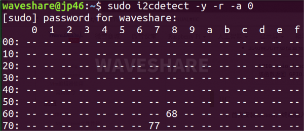
- Parameters: -y executes directly ignoring interactive prompts, -r is the SMBus read byte command, -a means all addresses, and 0 refers to SMBus 0.
-
Scan register data:
sudo i2cdump -y 0 0x68 -
Register Data Writing:
sudo i2cset -y 0 0x68 0x90 0x55-
Parameters:
Parameter Meaning 0 Represents the I2C device number 0x68 Represents the I2C device address 0x90 Represents the register address 0x55 Represents the data written to the register
-
-
Register Data Reading:
sudo i2cget -y 0 0x68 0x90-
Parameters:
Parameter Meaning 0 Represents the I2C device number 0x68 Represents the I2C device address 0x90 Represents the register address
-
Was this article helpful?