How to drive the module via Arduino board
Last revision 2026/01/20
The sketch for driving the GPS mode via the Arduino board.
How to drive the module via Arduino board
How to Send a message
| NOTE: Before you upload the sketch to the Arduino board, please turn the S2 switch to the Arduino side(left side), or you will not be able to register to the network. |
|---|
// Product name: GPS/GPRS/GSM Module V3.0
// # Product SKU : TEL0051
// # Version     : 0.1

// # Description:
// # The sketch for driving the gsm mode via the Arduino board

// # Steps:
// #        1. Turn the S1 switch to the Prog(right side)
// #        2. Turn the S2 switch to the Arduino side(left side)
// #        3. Set the UART select switch to middle one.
// #        4. Upload the sketch to the Arduino board
// #        5. Turn the S1 switch to the comm(left side)
// #        6. RST the board

// #        wiki link- https://www.dfrobot.com/wiki/index.php/GPS/GPRS/GSM_Module_V3.0_(SKU:TEL0051)

byte gsmDriverPin[3] = {
  3,4,5};//The default digital driver pins for the GSM and GPS mode
//If you want to change the digital driver pins
//or you have a conflict with D3~D5 on Arduino board,
//you can remove the J10~J12 jumpers to reconnect other driver pins for the module!
void setup()
{
  //Init the driver pins for GSM function
  for(int i = 0 ; i < 3; i  ){
    pinMode(gsmDriverPin[i],OUTPUT);
  }
  digitalWrite(5,HIGH);//Output GSM Timing
  delay(1500);
  digitalWrite(5,LOW);
  digitalWrite(3,LOW);//Enable the GSM mode
  digitalWrite(4,HIGH);//Disable the GPS mode
  delay(2000);
  Serial.begin(9600); //set the baud rate
  delay(5000);//call ready
  delay(5000);
  delay(5000);
}

void loop()
{
  Serial.println("AT"); //Send AT command
  delay(2000);
  Serial.println("AT");
  delay(2000);
  //Send message
  Serial.println("AT CMGF=1");
  delay(1000);
  Serial.println("AT CMGS=\"15800449871\"");//Change the receiver phone number
  delay(1000);
  Serial.print("HELLO");//the message you want to send
  delay(1000);
  Serial.write(26);
  while(1);
}
You can see:

After several seconds, the receiver will get a message from this shield
// Product name: GPS/GPRS/GSM Module V3.0
// # Product SKU : TEL0051

// # Description:
// # The sketch for controling the GSM/GPRS/GPS module via SMS.
// # Steps:
// #        1. Turn the S1 switch to the Prog(right side)
// #        2. Turn the S2 switch to the USB side(left side)
// #        3. Set the UART select switch to middle one.
// #        4. Upload the sketch to the Arduino board(Make sure turn off other Serial monitor )
// #        5. Turn the S1 switch to the comm(left side)
// #        6. Turn the S2 switch to the Arduino(right side)
// #        7. RST the board until the START led is on(make sure you have >6V power supply)
// #        8. Plug the long side of LED into pin 13 and short side into GND
// #        9. Start sending "LH" and "LL" to your board to turn LED on and off.

/*
 *  created:    2013-11-14
 *  by:     Grey
 *  Version:    0.3
 *  Attention: if you send the wrong SMS command to the module, just need to press RST.
 *  This version can't watch the module status via the serial monitor, it only display the Arduino command.
 *  If you want to watch the status,use the SoftwareSerial or the board with another serial port plese.
 */

byte gsmDriverPin[3] = {
  3,4,5};//The default digital driver pins for the GSM and GPS mode
//If you want to change the digital driver pins
//or you have a conflict with D3~D5 on Arduino board,
//you can remove the J10~J12 jumpers to reconnect other driver pins for the module!
int ledpin = 13;
char inchar;
void setup()
{
  //Init the driver pins for GSM function
  for(int i = 0 ; i < 3; i  ){
    pinMode(gsmDriverPin[i],OUTPUT);
  }
  pinMode(ledpin,OUTPUT);
  Serial.begin(9600);                                      //set the baud rate
  digitalWrite(5,HIGH);                                     //Output GSM Timing
  delay(1500);
  digitalWrite(5,LOW);
  digitalWrite(3,LOW);                                      //Enable the GSM mode
  digitalWrite(4,HIGH);                                     //Disable the GPS mode
  delay(2000);
  delay(5000);                                              //call ready
  delay(5000);
  Serial.println("AT CMGD=1,4");                           //Delete all SMS in box
}

void loop()
{
  if(Serial.available()>0)
  {
    inchar=Serial.read();
    if(inchar=='T')
    {
      delay(10);
      inchar=Serial.read();
      if (inchar=='I')                                      //When the GSM module get the message, it will display the sign ' CMTI "SM", 1' in the serial port
      {
        delay(10);
        Serial.println("AT CMGR=1");                       //When Arduino read the sign, send the "read" AT command to the module
        delay(10);
      }
    }
    else if (inchar=='L')
    {
      delay(10);
      inchar=Serial.read();
      if (inchar=='H')                                     //Thw SMS("LH") was display in the Serial port, and Arduino has recognize it.
      {
        delay(10);
        digitalWrite(ledpin,HIGH);                         //Turn on led
        delay(50);
        Serial.println("AT CMGD=1,4");                    //Delete all message
        delay(500);
      }
      if (inchar=='L')                                    //Thw SMS("LH") was display in the Serial port, and Arduino has recognize it.
      {
        delay(10);
        digitalWrite(ledpin,LOW);                         //Turn off led
        delay(50);
        Serial.println("AT CMGD=1,4");                   //Delete all message
        delay(500);
      }
    }
  }
}
When you send the SMS "LH" to the module, it WILL turn led on; when you send the SMS "LL", it will be turned off.
How to Make a phone call
// Product name: GPS/GPRS/GSM Module V3.0
// # Product SKU : TEL0051
// # Version     : 0.1

// # Description:
// # The sketch for driving the gsm mode via the Arduino board

// # Steps:
// #        1. Turn the S1 switch to the Prog(right side)
// #        2. Turn the S2 switch to the Arduino side(left side)
// #        3. Set the UART select switch to middle one.
// #        4. Upload the sketch to the Arduino board
// #        5. Turn the S1 switch to the comm(left side)
// #        6. RST the board

// #        wiki link- https://www.dfrobot.com/wiki/index.php/GPS/GPRS/GSM_Module_V3.0_(SKU:TEL0051)

byte gsmDriverPin[3] = {
  3,4,5};//The default digital driver pins for the GSM and GPS mode
//If you want to change the digital driver pins
//or you have a conflict with D3~D5 on Arduino board,
//you can remove the J10~J12 jumpers to reconnect other driver pins for the module!

void setup()
{
 //Init the driver pins for GSM function
  for(int i = 0 ; i < 3; i  ){
    pinMode(gsmDriverPin[i],OUTPUT);
  }
  digitalWrite(5,HIGH);//Output GSM Timing
  delay(1500);
  digitalWrite(5,LOW);
  digitalWrite(3,LOW);//Enable the GSM mode
  digitalWrite(4,HIGH);//Disable the GPS mode
  delay(2000);
  Serial.begin(9600); //set the baud rate
  delay(5000);//call ready
  delay(5000);
  delay(5000);
}

void loop()
{
   Serial.println("AT");//Send AT command
   delay(2000);
   Serial.println("AT");
   delay(2000);
  //Make a phone call
   Serial.println("ATD15902808530;");//Change the receiver phone number
   while(1);
}
You can see: 
After several seconds,the receiver will get a phone call from this shield
How to drive the GPS Mode via Arduino board
- S1 - Comm
- S2 - Arduino
- S3 - UART ( Middle)
Sample code could be found here.
Project Sharing
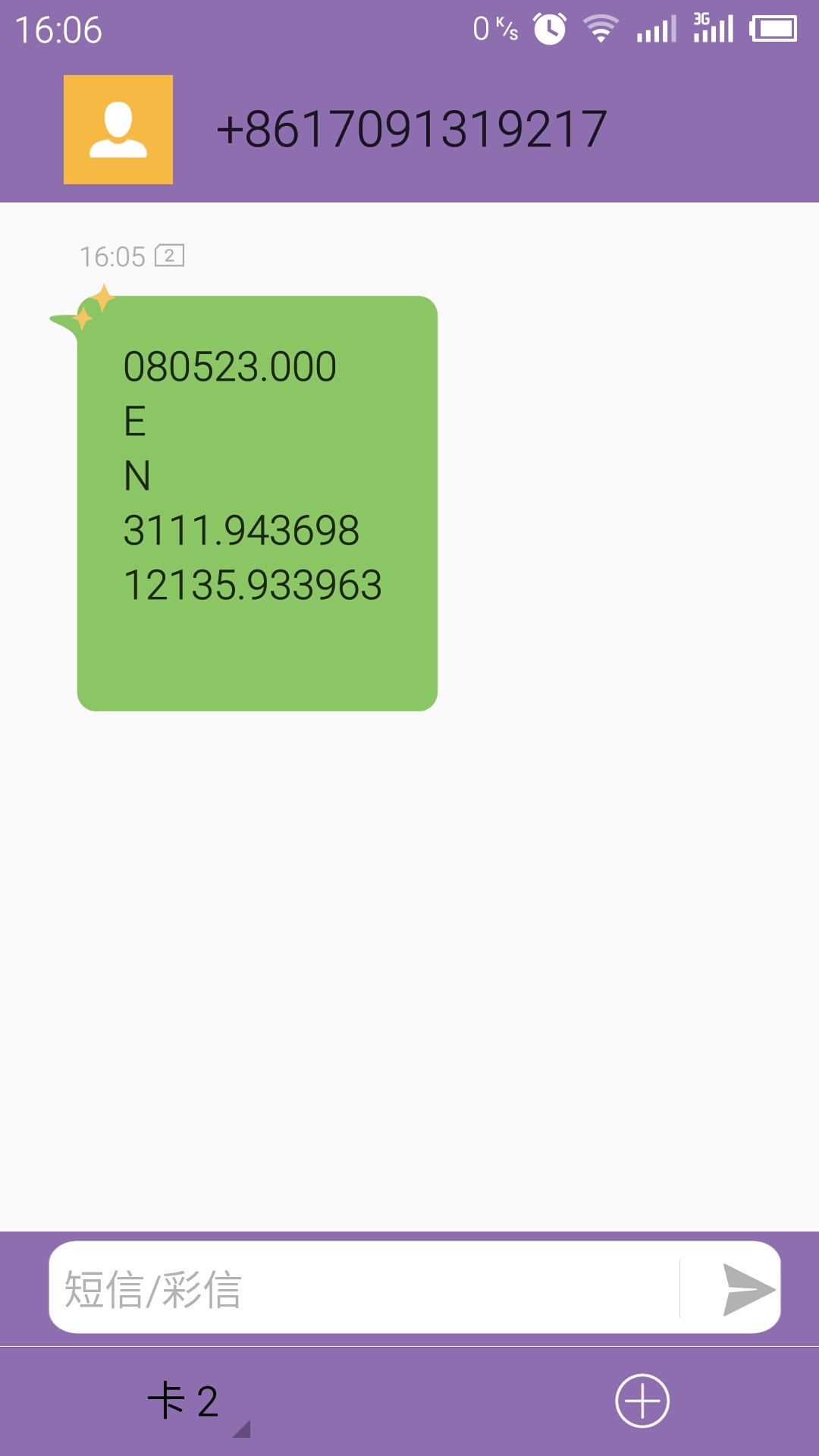
This code will send GPS information to your phone via SMS. As the picture at right hand.
- Please download the library.
- Fill your phone number into the code.
- Upload the sketch to your Arduino board, after about 5-10 minutes according to your GPS signal intensity.
Was this article helpful?