Getting Started: Sketch Upload and AT Mode Setup
Last revision 2026/01/20
Requirements
- Hardware
- Arduino Uno
- GPS/GPRS/GSM Module V3.0
- SIM Card
- Earphone & Microphone
- External power supply, 7-12V@2A
- Software
- Coolterm or
DF Serial Debugger by Lisper, we use the first one in the wiki. - Arduino IDE, any version is fine, Click to Download Arduino IDE
- Coolterm or
Sample Code
- Click here to download.
Getting Started: Upload Sketch and Enter AT Mode
1. How to upload a sketch to Arduino card once got the module stacked on?
The module will occupy the serial port if you switch S1 to Comm, so once you release the serial port by switching S1 to Prog, you could upload a sketch in normal.
2. How to enter AT mode, sending AT command?
1.Insert an available SIM card onto the module (not necessary for GPS test), stack the module on Uno, then use a USB cable to connect Uno to PC. PWR LED will turn on as red.
If you want to test GSM function like send a message, call somebody... you have to supply UNO with an external power.
2.Open Arduino IDE, choose "board" & "port" in Menu bar.
3.Upload code to disable/ enable different function of this module according to your test, seen in following specific section.
4.Check the switch position, S1: Comm; S2: USB; S3: for gps AT test_GSM OR for gsm AT test_middle.
5.Open Arduino serial monitor or use other serial helper (Coolterm is used here, for Arduino serial monitor can not send command in HEX).
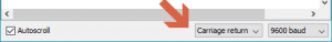
6.Choose "9600" & "Both NL&CR" (or "Carriage Return") as the command format.
7.If the STAT & NET LED turned off, please hit the button RST to reboot the module.
8.After the STAT LED is on, and some RDY(ready) notices printed on your screen, then you could send AT commands to use the module.
Serial Command Format setting
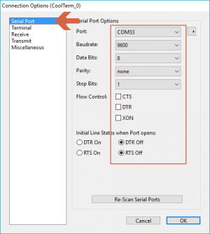
CoolTerm Serial command setting:"9600"
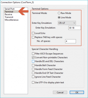
CoolTerm Serial command setting "CR LF" or "CR"
Arduino IDE Serial command setting: "9600" & "Both NL&CR" (or "Carriage Return")
3. About GSM mode & GPS mode Selection
Except using UART selection jumper caps(old version)/ the switch(latest version), alternatively, you could also switch GSM and GPS function with the IO pins, but please remove the jumper caps connected for hardware UART selection(old version)/ set the switch in middle(latest version) in this case.
digitalWrite(4,LOW);//Enable GPS mode
digitalWrite(3,HIGH);//Disable GSM mode
digitalWrite(3,LOW);//Enable GSM mode
digitalWrite(4,HIGH);//Disable GPS mode
| NOTE: You could control GPS through the GSM AT commands, without requiring to enable both independently. This way you can let the GPS enabled while using GSM network. Thus not triggering a GPS reset. |
|---|
Was this article helpful?