Example Code for Arduino-Data interrupt function
Data interrupt function
Hardware Preparation
- Firebeetle Board-M0 x 1
- BMP390L digital barometric pressure sensor × 1
- Jumper wires
Software Preparation
- Arduino IDE
- Download and install the Library files and sample programs. (About how to install the library?)
- Or get Library files from Arduino :


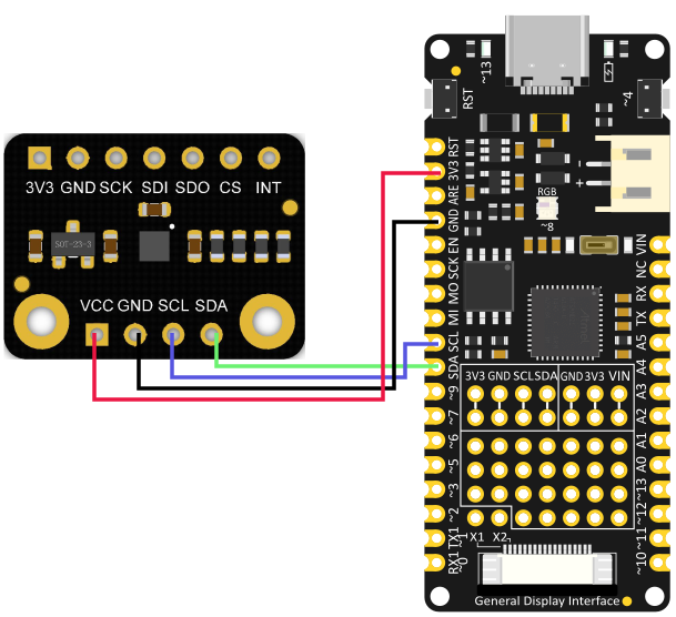
Wiring Diagram
Sample Code
-
Choose interruptDataDrdy.ino

-
Burning program
/*!
 * @file interruptDataDrdy.ino
 * @brief Demonstrate ready data (temperature/pressure) interrupt
 * @n When measured data, the sensor will generate a 2.5 ms pulse signal by INT in the non-interrupt
 * @n register locked state.
 * @copyright   Copyright (c) 2010 DFRobot Co.Ltd (http://www.dfrobot.com)
 * @licence     The MIT License (MIT)
 * @author [qsj]([email protected])
 * @version  V0.1
 * @date  2021-4-30
 * @get from https://www.dfrobot.com
 * @url https://github.com/DFRobot/DFRobot_BMP3XX
 */
#include <DFRobot_BMP3XX.h>

/**
* Select chip version BMP388/BMP390L
* Select IIC communication interface, please comment out SPI interface.
* IIC communication address settings: eSDOGND: connect SDO pin to GND, I2C address is 0×76 now.
*                   eSDOVDD: Connect SDO pin to VDDIO (3v3), I2C address is 0×77 now
* Notice: If using Gravity products, default IIC communication address is: 0×77(eSDOVDD)
*/
//DFRobot_BMP388_IIC sensor(&Wire, sensor.eSDOVDD);
 DFRobot_BMP390L_IIC sensor(&Wire, sensor.eSDOVDD);

/**
* Select the chip version BMP388/BMP390L
* Select IIC communication interface, please comment out SPI interface.
* Set up digital pin according to the on-board pin connected with SPI chip-select pin.
* Notice: csPin used here is D3 digital pin on ESP32, other non-conflicting pins can also be selected
* as external interrupt pins.
*/
// uint8_t csPin = D3;
// DFRobot_BMP388_SPI sensor(&SPI, csPin);
// DFRobot_BMP390L_SPI sensor(&SPI, csPin);


/* If you do not need to eliminate the absolute difference of measurement, please comment the following line */
#define CALIBRATE_ABSOLUTE_DIFFERENCE

/* Interrupt flag */
volatile uint8_t flag = 0;
/* External interrupt flag */
void interrupt()
{
  if(flag ==0){
    flag = 1;
  }
}

void setup(void)
{
  Serial.begin(115200);

  int rslt;
  while( ERR_OK != (rslt = sensor.begin()) ){
    if(ERR_DATA_BUS == rslt){
      Serial.println("Data bus error!!!");
    }else if(ERR_IC_VERSION == rslt){
      Serial.println("Chip versions do not match!!!");
    }
    delay(3000);
  }
  Serial.println("Begin ok!");

  /**
  * Interrupt configuration
  * mode The interrupt mode needs to set. The following modes add up to mode:
  *      Interrupt pin output mode: eINTPinPP: Push pull, eINTPinOD: Open drain
  *      Interrupt pin active level: eINTPinActiveLevelLow: Active low, eINTPinActiveLevelHigh: Active high
  *      Register interrupt latch: eINTLatchDIS: Disable, eINTLatchEN: Enable
  *      FIFO water level reached interrupt: eINTFWTMDIS: Disable, eINTFWTMEN: Enable
  *      FIFO full interrupt: eINTFFullDIS: Disable, eINTFFullEN: Enable
  *      Interrupt pin initial (invalid, non-interrupt) level: eINTInitialLevelLOW: Low, eINTInitialLevelHIGH: High
  *      Temperature/pressure data ready interrupt: eINTDataDrdyDIS: Disable, eINTDataDrdyEN: Enable
  * Notice: In non-latching mode (eINTLatchDIS), interrupt signal is 2.5 ms pulse signal
  * Note: When using eINTPinActiveLevelLow (Active low interrupt pin), you need to use eINTInitialLevelHIGH (Initial
  *       level of interrupt pin is high). Please use “FALLING” to trigger the following interrupt.
  *       When using eINTPinActiveLevelHigh (Active low interrupt pin), you need to use eINTInitialLevelLOW (Initial
  *       level of interrupt pin is high). Please use “RISING” to trigger the following interrupt.
  */
  sensor.setINTMode(sensor.eINTPinPP +
                    sensor.eINTPinActiveLevelHigh +
                    sensor.eINTLatchDIS +
                    sensor.eINTFWTMDIS +
                    sensor.eINTFFullDIS +
                    sensor.eINTInitialLevelLOW +
                    sensor.eINTDataDrdyEN);

  delay(100);
  #ifdef CALIBRATE_ABSOLUTE_DIFFERENCE
  /**
  * Calibrate the sensor according to the current altitude
  * In this example, we use an altitude of 540 meters in Wenjiang District of Chengdu (China).
  * Please change to the local altitude when using it.
  * If this interface is not called, the measurement data will not eliminate the absolute difference
  * Note: This interface is only valid for the first call
  */
  if( sensor.calibratedAbsoluteDifference(540.0) ){
    Serial.println("Absolute difference base value set successfully!");
  }
  #endif

  #if defined(ESP32) || defined(ESP8266)
  //D6 pin is used as interrupt pin by default, other non-conflicting pins can also be selected as external
  //interrupt pins.
  attachInterrupt(digitalPinToInterrupt(D6)/*Query the interrupt number of the D6 pin*/,interrupt,CHANGE);
  #elif defined(ARDUINO_SAM_ZERO)
  //Pin 5 is used as interrupt pin by default, other non-conflicting pins can also be selected as external
  // interrupt pins
  attachInterrupt(digitalPinToInterrupt(5)/*Query the interrupt number of the 5 pin*/,interrupt,CHANGE);
  #else
  /*    The Correspondence Table of AVR Series Arduino Interrupt Pins And Terminal Numbers
   * ---------------------------------------------------------------------------------------
   * |                                        |  DigitalPin  | 2  | 3  |                   |
   * |    Uno, Nano, Mini, other 328-based    |--------------------------------------------|
   * |                                        | Interrupt No | 0  | 1  |                   |
   * |-------------------------------------------------------------------------------------|
   * |                                        |    Pin       | 2  | 3  | 21 | 20 | 19 | 18 |
   * |               Mega2560                 |--------------------------------------------|
   * |                                        | Interrupt No | 0  | 1  | 2  | 3  | 4  | 5  |
   * |-------------------------------------------------------------------------------------|
   * |                                        |    Pin       | 3  | 2  | 0  | 1  | 7  |    |
   * |    Leonardo, other 32u4-based          |--------------------------------------------|
   * |                                        | Interrupt No | 0  | 1  | 2  | 3  | 4  |    |
   * |--------------------------------------------------------------------------------------
   */
  /*                      The Correspondence Table of micro:bit Interrupt Pins And Terminal Numbers
   * ---------------------------------------------------------------------------------------------------------------------------------------------
   * |             micro:bit                       | DigitalPin |P0-P20 can be used as an external interrupt                                     |
   * |  (When using as an external interrupt,      |---------------------------------------------------------------------------------------------|
   * |no need to set it to input mode with pinMode)|Interrupt No|Interrupt number is a pin digital value, such as P0 interrupt number 0, P1 is 1 |
   * |-------------------------------------------------------------------------------------------------------------------------------------------|
   */
  attachInterrupt(/*Interrupt No*/0,interrupt,CHANGE);//Open the external interrupt 0, connect INT1/2 to the digital pin of the main control:
     //UNO(2), Mega2560(2), Leonardo(3), microbit(P0).
  #endif

  /* Get the sampling period of the current measurement mode, unit: us */
  float sampingPeriodus = sensor.getSamplingPeriodUS();
  Serial.print("samping period : ");
  Serial.print(sampingPeriodus);
  Serial.println(" us");

  /* Get the sampling frequency of the current measurement mode, unit: Hz */
  float sampingFrequencyHz = 1000000 / sampingPeriodus;
  Serial.print("samping frequency : ");
  Serial.print(sampingFrequencyHz);
  Serial.println(" Hz");

  Serial.println();
  delay(1000);
}

void loop()
{
  if(flag == 1){
    flag = 0;
    /* When data is ready and the interrupt is triggered, read altitude, unit: m */
    float altitude = sensor.readAltitudeM();
    Serial.print("Altitude : ");
    Serial.print(altitude);
    Serial.println(" m");
  }
}
Result

Additional Information
**Notice: **The tutorial example uses an altitude of 540 meters in Wenjiang District, Chengdu (China). Please change to the local altitude calibration when actually using it.
Was this article helpful?