Romeo Robot Control Board

SKU: DFR0004

The Romeo Robot Control Board is an all-in-one robotics solution from DFRobot, designed for ease of use with the Arduino platform. It features integrated 2x2A DC motor drivers, a wireless communication socket, and extra power for servos, making it ideal for building custom robots. Compatible with Gravity series sensors and actuators, the board offers plug-and-play capabilities for hundreds of sensors. As the first Arduino-derived board, Romeo has a rich history of supporting robotics applications since its inception in 2009. With its current version based on Arduino Uno, Romeo continues to be a powerful tool for robotics enthusiasts, offering seamless integration and expansion possibilities.

Angled shot of Romeo motor driver board with Arduino interface-DFRobot product sku:DFR0004 image.

Downloadable Resources

  • Docs
  • Tech Specs
  • Blog
  • Specification

    Parameter Details
    Microcontroller Atmega 168/328
    Digital I/O 14 Channels
    PWM Channels 6 (Pin11, Pin10, Pin9, Pin6, Pin5, Pin3)
    Analog I/O 8 Channels 10-bit
    Interface USB interface
    Power Input Auto sensing/switching power input
    Programming ICSP header for direct program download
    Serial Interface TTL Level
    Special Features Support AREF; Support Male and Female Pin Header
    Integrated Sockets APC220 RF Module and DF-Bluetooth Module
    I2C Interface Five Pin Sets
    Motor Drive Two way, 2A maximum current
    Key Inputs 5
    DC Supply USB Powered or External 7V~12V DC
    DC Output 5V /3.3V DC and External Power Output
    Dimension 90x80mm

    Pinout

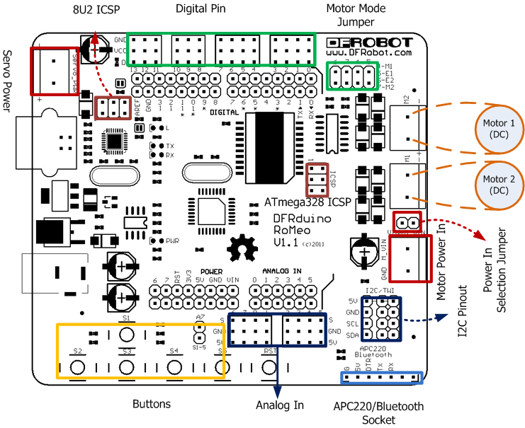
    Fig1: Romeo Pin Out
    The picture above shows all of the I/O lines and Connectors on the Romeo, which includes:

    • One Regulated Motor Power Input Terminal (6v to12v)
    • One Unregulated Servo Power Input Terminal (you supply regulated 4v to 7.2v)
    • One Servo input power selection jumper
    • One Serial Interface Module Header for APC220/Bluetooth Module
    • Two DC Motor Terminals – Handles motor current draw up to 2A, each terminal
    • One I2C/TWI Port – SDA, SCL, 5V, GND
    • One Analog Port with 8 analog inputs – Analog input 7 will be occupied when connecting "A7" jumper
    • One General Purpose I/O Port with 13 I/O lines – 4,5,6,7 can be used to control motors
    • One Reset Button
    • Jumper bank to Enable/Disable Motor Control

    Was this article helpful?

    TOP