Introduction
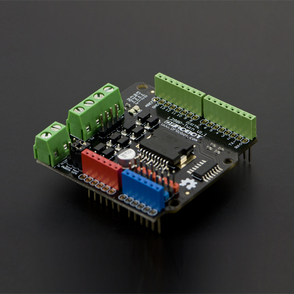
This motor shield allows Arduino to drive two channel DC motors. It uses a L298N chip which deliveries output current up to 2A each channel.
Specifications
- Motor Driven Voltage: 4.8V to 35V
- Output Current: up to 2A/channel
- Total Power Dissipation: 25W(T=75℃)
- Driven Structure: Dual full-bridge driver
- Driven Power Port: External power terminal, or VIN from Arduino
- Driven Output Port: 2 channel screw terminals, or male PIN headers
- Control Port: 4 TTL Compatible digital signals (Digital 10-13)
- Operation Temperature: -25℃ to 130℃
- Shield Size: 56x57mm
Application
- Electric toy car
PinOut

-
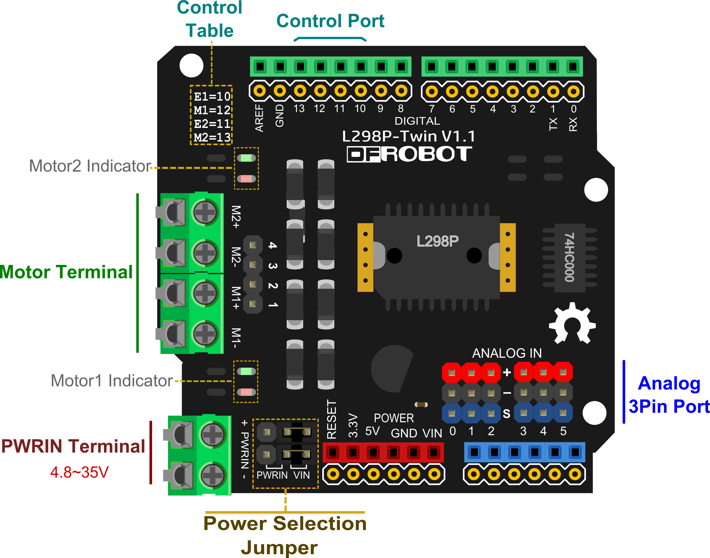
Power Selection Jumper: The motors can be powered by external power supply(PWMIN) or VIN from Arduino control board(e.g., UNO). Default is VIN showed by the diagram. Note: There are two jumpers in parallel that can afford heavy current.
-
PWMIN Terminal: Used to connect to external power.
-
Motor Terminal: Used to connect motors by screw terminals(M1- M1+ M2- M2+) or PIN headers(1 2 3 4).
-
Analog 3Pin Port: Used to connect sensors or actuators. Note: pinout is (+ - S).
-
Motor Indicator: The red LED lights if Mn+ is positive, whereas the green LED lights.
-
Control Port: Used to control speed and direction of motor. You can get port's description in the "Control Table" printed on the shield.
-
Control Function Table:
| Name | Function |
|---|---|
| En | Mn Speed control(PWM) |
| Mn | Mn Direction Control |
- Control Signal Truth Table:
| En | Mn | State |
|---|---|---|
| L | X | Disable Mn |
| H | L | Mn Foreward(Mn+ is positive) |
| H | H | Mn Backward(Mn+ is negative) |
Note: n of "Mn" or "En" is 1, 2
Tutorial
DC Motor Control
Target: Control speed and direction of DC motor
Step1: Hardware List
- DF_UNO 1
- Micro Metal Gearmotor 2
- Regulated Power 1
- The Shield 1
- Wires
Step2: Software List
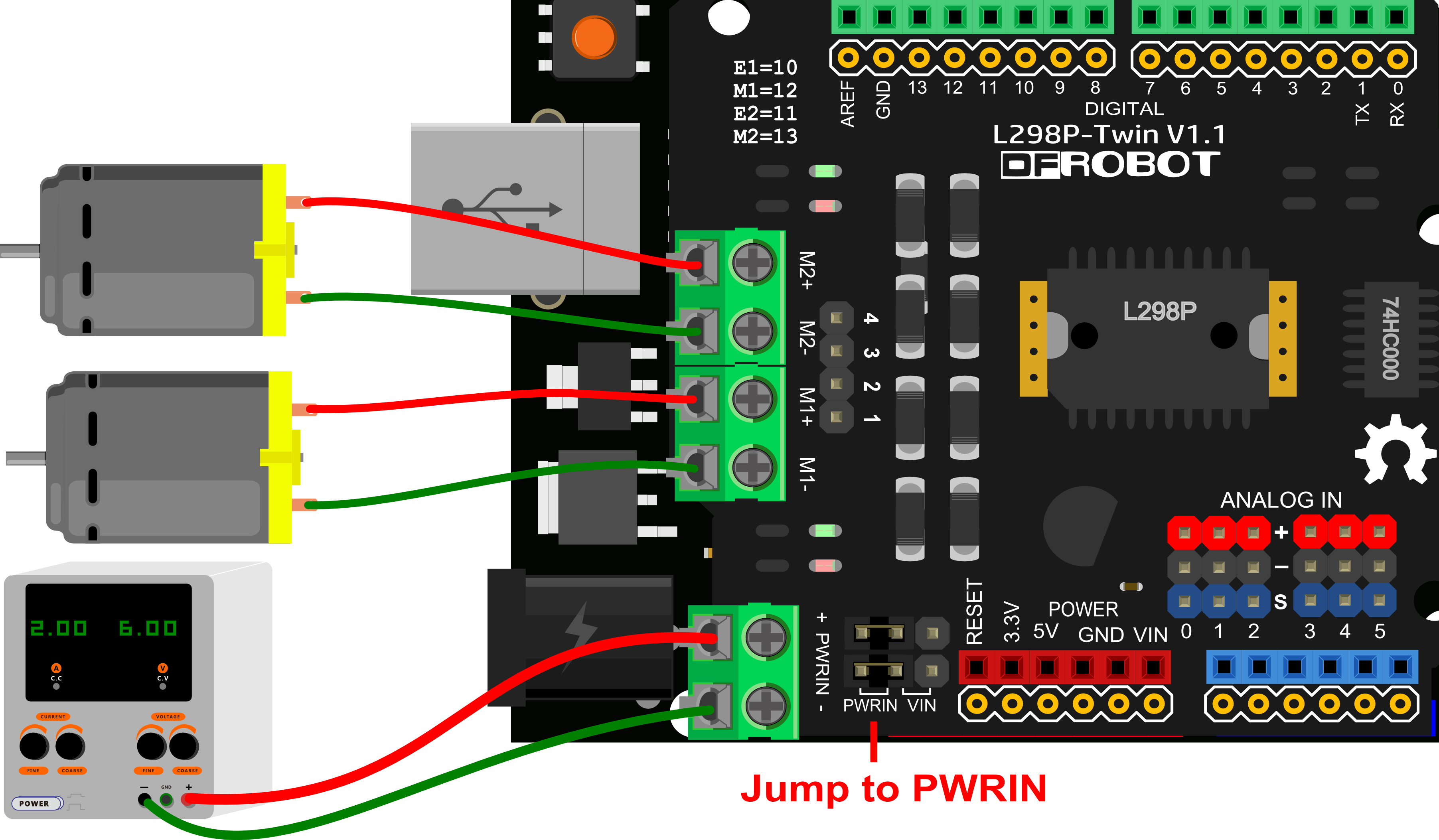
Step3: Wiring

Step4: Sample Code
- Open Arduino IDE
- Upload the code to UNO
/**set control port**/
const int E1Pin = 10;
const int M1Pin = 12;
const int E2Pin = 11;
const int M2Pin = 13;

/**inner definition**/
typedef struct {
  byte enPin;
  byte directionPin;
} MotorContrl;

const int M1 = 0;
const int M2 = 1;
const int MotorNum = 2;

const MotorContrl MotorPin[] = { {E1Pin, M1Pin}, {E2Pin, M2Pin} } ;

const int Forward = LOW;
const int Backward = HIGH;

/**program**/
void setup() {
  initMotor();
}

void loop() {
  int value;
  /**test M1 **/
  setMotorDirection( M1, Forward );
  setMotorSpeed( M1, 100 );
  delay(1000);
  setMotorSpeed( M1, 0 );
  delay(100);

  setMotorDirection( M1, Backward );
  setMotorSpeed( M1, 50 );
  delay(1000);
  setMotorSpeed( M1, 0 );
  delay(100);

  /**test M2**/
  setMotorDirection( M2, Backward );
  for (value = 0 ; value <= 100; value += 5) {
    setMotorSpeed( M2, value );
    delay(100);
  }
  setMotorSpeed( M2, 0 );
  setMotorDirection( M2, Forward );
  for (value = 0 ; value <= 100; value += 5) {
    setMotorSpeed( M2, value );
    delay(100);
  }
  setMotorSpeed( M2, 0 );
}

/**functions**/
void initMotor( ) {
  int i;
  for ( i = 0; i < MotorNum; i++ ) {
    digitalWrite(MotorPin[i].enPin, LOW);

    pinMode(MotorPin[i].enPin, OUTPUT);
    pinMode(MotorPin[i].directionPin, OUTPUT);
  }
}

/**  motorNumber: M1, M2
direction:          Forward, Backward **/
void setMotorDirection( int motorNumber, int direction ) {
  digitalWrite( MotorPin[motorNumber].directionPin, direction);
}

/** speed:  0-100   * */
inline void setMotorSpeed( int motorNumber, int speed ) {
  analogWrite(MotorPin[motorNumber].enPin, 255.0 * (speed / 100.0) ); //PWM
}
Step5: Result
M1 will forward at full speed, and then half speed inversion; M2 velocity from fast to slow, reverse first, and then forward.
FAQ
More question and cool idea, visit DFRobot Forum
