Introduction
In most Arduino projects, relays are the first and easiest choice to drive large current devices. It requires a certain amount of current to drive the internal coil to pick-up contact, ut for some MCU, like Intel Edison, Intel joule, lilypad, Raspberry Pi and other microcontroller with limited amount of current GPIO, it’s hard to drive one or more relays simultaneously.
The MOSFET power controller is a module which can drive a large current device with limited current GPIO. It works as a MOSFET relay or MOSFET driver. When you give it a digital high-level signal (3.3~10V), MOSFET turns on, and vice versa.
Compared to a relay module, MOSFET power controller is compatible with Arduino Raspberry Pi, Lattepanda and other Microcontroller and supports 3.3~10V logic power control. The VIN port supports 5~36V; 0~20A power input, if the current is over 10A, we recommend an external heat sink. Additionally, our MOSFET module supports a quick ON-OFF switch at a switching frequency of 1KHz. This is especially helpful in many robotic projects that require high precision drivers. When controlling high-power inductive loads (such as electromagnets, motors, solenoids, etc.), a freewheeling diode should be added to prevent back electromotive force (back EMF) from damaging the MOSFET.
The MOSFET power controller comes with a standard PH2.0-3P gravity interface. It makes the module compatible with the Arduino IO expansion shield. In the the end the module is plug and play ready and easy to use.
Specification
- VIN Operating Voltage: 5V-36V DC
- VIN Operating Current: 0A-20A (Suggest external heat sink when the current over 10A )
- Logic Operating Voltage: 3.3~10V DC
- Logic Control Signal: 3.3~10V DC
- Switching Frequency: 0-1KHz
- Switching Character: T(on)=20us/T(off)=50us
- Operating Temperature: -55℃-155℃
- Interface Type: PH2.0-3P
- Dimension: 4432 mm/ 1.731.26 inches
- Mounting Hole Size: inner diameter 3.1mm/0.12"; outer diameter 6mm/0.24"
Board Overview

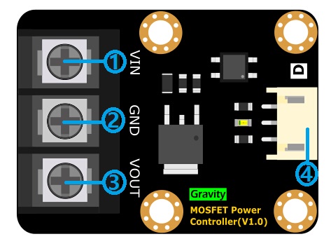
| Num | Name | Description |
|---|---|---|
| 1 | VIN | Power Input (DC:5~36V) |
| 2 | GND | GND |
| 3 | VOUT | Power Output |
| 4 | PH2.0-3Pin | Gravity Interface |
Tutorial
This tutorial demonstrates the module usage. It could be finished in 10 minutes
Requirements
-
Hardware
- DFRduino UNO x 1
- MOSFET Power Controller x1
- 24V DC Lamp x1
- DC power supply x1
- M-M/F-M/F-F Jumper wires
-
Software
- Arduino IDE, Click to Download Arduino IDE from Arduino®
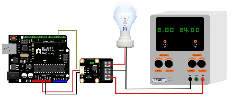
Connection Diagram

Sample Code
This demo code is used to turn on/off lamp through our product.(We provide 3.3V for the mudule here.)
/*
* @DFRobot
* @author Hudianjiang
* @version  V1.0
* @date  2016-8-30
*/
const int LampControl=3;                   //define var
void setup() {
  pinMode(LampControl,OUTPUT);            // Set pinMode
}
void loop() {
  digitalWrite(LampControl,HIGH);//Light up lamp 2s
  delay(2000);
  digitalWrite(LampControl,LOW);//Turn off lamp 2s
  delay(2000);
}
Expected Results
The lamp will blink like an led (This is a demo, we do not suggest you operate your lamp like this continually, since it will reduce the service life.)
FAQ
| For any questions, advice or cool ideas to share, please visit the DFRobot Forum. |
|---|
