Introduction
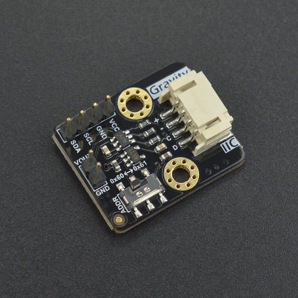
DFRobot Gravity 12-Bit I2C DAC is a small and easy-to-use 12-bit digital-to-analog converter with EEPROM. It can accurately convert the digital value to corresponding analog voltage signal, which is useful in may creative projects and automatic control systems. Although an analog voltage signal can be generated by PWM with traditional controllers such as Arduino and Raspberry Pi, such signal is ROUGH and NOT ACCURATE. To obtain a steady and nice analog voltage signal, the DAC is the best candidate. In addition to be applied in automatic control systems, the DAC module can be use to serve as a function generator to generate sine wave, triangular wave and even arbitrary waveform (we provide a library to generate low frequency sin and triangular wave with just a few parameters).
The module employs a 12-bit DAC MCP4725. It requires no external reference voltage (DAC reference is driven from VCC directly), supports 3.3V~5V wide input voltage and has a I2C address selection switch (two address 0x60 and 0x61 are available, which support maximum two modules in cascade). The EEPROM can retain the DAC input while power-off and resume the DAC output upon power-on.
Features
- 12-bit High Accuracy DAC
- On-Board EEPROM, Retain DAC Input While Power-Off
- Gravity I2C Interface, Plug and Play. XH2.54 4P Reserved for Expansion
- Wide Voltage Input, Compatible with 3.3V and 5V Controller
- Small Size and Easy to Install
Applications
- Sensor Calibration
- Automatic Control Systems
- Function Generator
Specifications
- Input Voltage (VCC): 3.3V~5.0V
- Output Voltage: 0 ~ VCC
- Resolution: 12-bit
- Working Current: <0.2 mA
- Interface: Gravity I2C (logic level: 0-3.3V)
- Dimension: 27.0mm*22.0mm
Board Overview
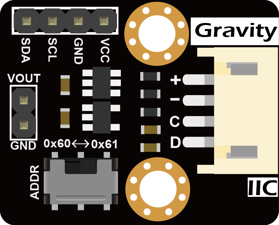
| Label | Name | Description |
|---|---|---|
| + | VCC | Power VCC(3.3~5.0V) |
| - | GND | Power GND |
| C | SCL | I2C Clock Signal |
| D | SDA | I2C Data Signal |
| ADDR | I2C address | I2C address selection switch(0x60 or 0x61) |
| VOUT | VOUT | DAC analog voltage output(0~VCC) |
Arduino Tutorial
Requirements
-
Hardware
- DFRduino UNO R3 (or similar) x 1
- DFRobot Gravity: 12-Bit I2C DAC Module x 1
- Gravity 4P sensor wire (or Dupont wires) x 1
- Digital multimeter (optional) x 1
- Oscilloscope (optional) x 1
-
Software
- Arduino IDE (V1.0.x or V1.8.x), Click to Download Arduino IDE from Arduino®
- Download and install the MCP4725 Library. How to install the library?
Connection Diagram
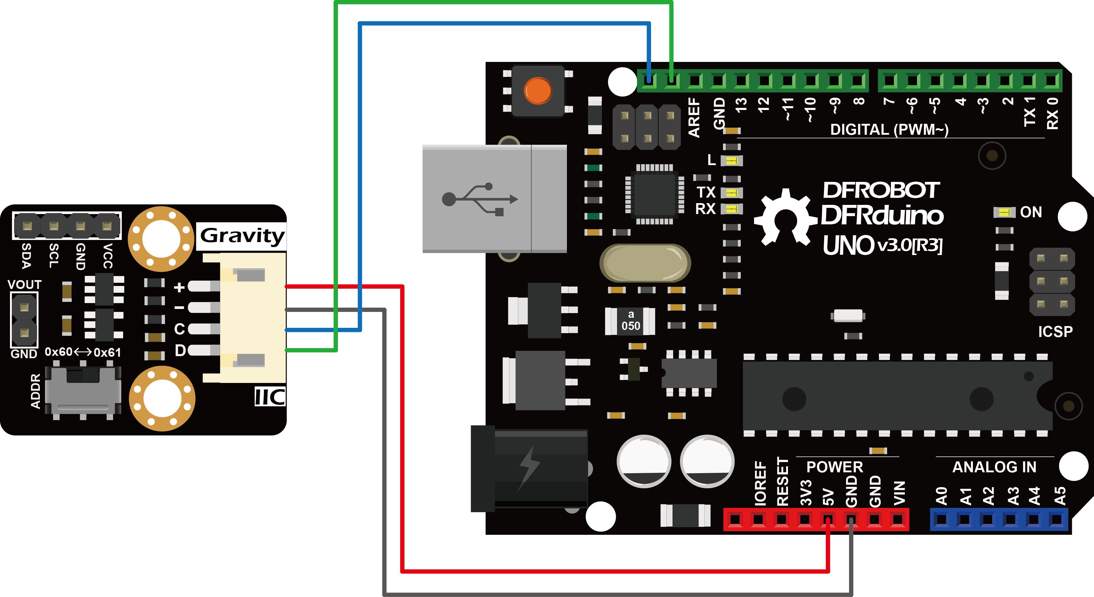
Calibration and adjustable analog voltage output
Although the DAC's voltage output accuracy is affected by several factors that cause the actual output voltage to deviate from the user-specified voltage values, the DAC reference voltage, Vref, of the MCP4725 is the same as the supply voltage VCC, and the supply voltage is usually not accurate (the actual voltage is not exactly 5.000 V or 3.300V), which results in large output error. Here, we provide a simple calibration method to eliminate the error caused by the inaccurate reference voltage. If calibration is not carried out, users can still simply set REF_VOLTAGE to 5000 in the code below (for a 5V controller such as an Arduino) or 3300 (for a 3.3V controller such as Raspberry Pi, FireBeetle) depending on the controller used.
Users are required an additional high-precision digital multimeter to complete the calibration, the specific steps are as follows:
- Connect the module to the Arduino according to the connection diagram above and set I2C address to 0x60 by ADDR switch on the module. If I2C address 0x61 is preferred, you need to modify the first parameter of the function DAC.init() in the code below.
- Install the MCP4725 library
- Open Arduino IDE and upload the following code to Arduino UNO
- Use the multimeter to measure the output voltage of VOUT and change the value of REF_VOLTAGE accordingly. For example, VOUT = 4950mV, the "#define REF_VOLTAGE 5000" should be revised to "#define REF_VOLTAGE 4950". Calibration completed.
- Change the value of OUTPUT_VOLTAGE (unit in mV) to your desired analog output voltage. This value should be smaller than REF_VOLTAGE or the maximum output voltage will be limited to REF_VOLTAGE. Before using the sample code below, write the calibration value to REF_VOLTAGE first to get a more accurate output voltage.
/*
 * file OutputVoltage.ino
 *
 * @ https://github.com/DFRobot/DFRobot_MCP4725
 *
 * connect MCP4725 I2C interface with your board (please reference board compatibility)
 *
 * Output a constant voltage value and print through the serial port.
 *
 * Copyright   [DFRobot](https://www.dfrobot.com), 2016
 * Copyright   GNU Lesser General Public License
 *
 * version  V1.0
 * date  2018-1-15
 */
#include "DFRobot_MCP4725.h"
#define  REF_VOLTAGE    5000

DFRobot_MCP4725 DAC;

uint16_t OUTPUT_VOLTAGE = 5000;        // Input DAC output voltage (0~REF_VOLTAGE,unit: mV)

void setup(void) {

  Serial.begin(115200);
  /* MCP4725A0_address is 0x60 or 0x61
   * MCP4725A0_IIC_Address0 -->0x60
   * MCP4725A0_IIC_Address1 -->0x61
   */
  DAC.init(MCP4725A0_IIC_Address0, REF_VOLTAGE);

}

void loop(void) {

  Serial.print("DFRobot_MCP4725 output: ");
  Serial.print(OUTPUT_VOLTAGE);
  Serial.println(" mV");

  DAC.outputVoltage(OUTPUT_VOLTAGE);

  delay(500);
}
Store the DAC Value in EEPROM
- Set the I2C address to 0x60 with the ADDR switch. For I2C address 0x61, you need to modify the first parameter of the function DAC.init () in the code below.
- Open Arduino IDE, upload the following sample code to the Arduino UNO, and use a digital multimeter to measure the output voltage of VOUT.
- The user can change the value of OUTPUT_VOLTAGE to change the analog voltage output. REF_VOLTAGE can be set to the value used in the Calibration section. If not calibrated, simply set it to 5000 (for 5V controllers such as Arduino) or 3300 (for 3.3V controller such as Raspberry Pi, FireBeetle etc.) .
/*
 * file OutputVoltageEEPROM.ino
 *
 * @ https://github.com/DFRobot/DFRobot_MCP4725
 *
 * connect MCP4725 I2C interface with your board (please reference board compatibility)
 *
 * Output a constant voltage value and write to the internal EEPROM.
 *
 * Copyright   [DFRobot](https://www.dfrobot.com), 2016
 * Copyright   GNU Lesser General Public License
 *
 * version  V1.0
 * date  2018-1-15
 */
#include "DFRobot_MCP4725.h"
#define  REF_VOLTAGE    5000

DFRobot_MCP4725 DAC;

uint16_t OUTPUT_VOLTAGE = 1000;        // Input DAC output voltage (0~REF_VOLTAGE,unit: mV)

void setup(void) {

  Serial.begin(115200);
  /* MCP4725A0_address is 0x60 or 0x61
   * MCP4725A0_IIC_Address0 -->0x60
   * MCP4725A0_IIC_Address1 -->0x61
   */
  DAC.init(MCP4725A0_IIC_Address0, REF_VOLTAGE);

}

void loop(void) {

  Serial.print("DFRobot_MCP4725 write to EEPROM and output: ");
  Serial.print(OUTPUT_VOLTAGE);
  Serial.println(" mV");

  DAC.outputVoltageEEPROM(OUTPUT_VOLTAGE);

  delay(200);
}
Results
- A 1V voltage signal can be measured at VOUT. Disconnect the module from the Arduino. Repower the module, by connecting oinly the VCC and GND pins of the module to 5V and GND on the Arduino, respectively. The user can still read 1V at VOUT. The function DAC.outputVoltageEEPROM () stores the DAC value in the EEPROM while it outputs a specified analog voltage signal. The module recalls the DAC value in the EEPROM upon power-up and restores the analog output at VOUT.
Output a Sine Wave
- Set the I2C address to 0x60 with the ADDR switch. For I2C address 0x61, you need to modify the first parameter of the DAC.init () function in the code below.
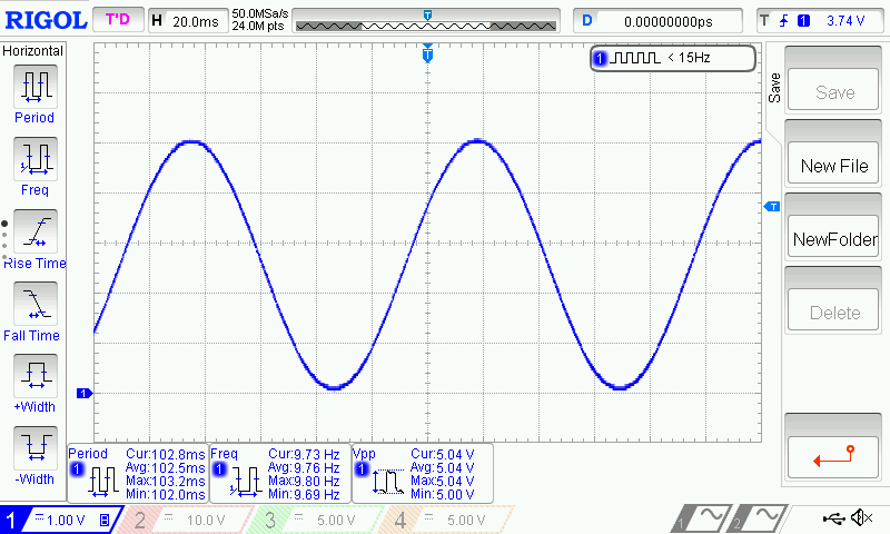
- Open Arduino IDE, upload the following sample code to the Arduino UNO, and use a oscilloscope to measure the output voltage of VOUT.
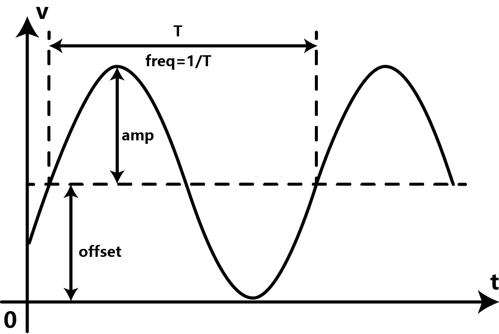
- The user can modify the parameters in the function DAC.outputSin () to change the amplitude, frequency and DC offset of the sine wave.
/*
 * file OutputVoltage.ino
 *
 * @ https://github.com/DFRobot/DFRobot_MCP4725
 *
 * connect MCP4725 I2C interface with your board (please reference board compatibility)
 *
 * Output a constant voltage value and print through the serial port.
 *
 * Copyright   [DFRobot](https://www.dfrobot.com), 2016
 * Copyright   GNU Lesser General Public License
 *
 * version  V1.0
 * date  2018-1-25
 */
#include "DFRobot_MCP4725.h"
#define  REF_VOLTAGE    5000

DFRobot_MCP4725 DAC;

void setup(void) {
  Serial.begin(115200);
  /* MCP4725A0_address is 0x60 or 0x61
   * MCP4725A0_IIC_Address0 -->0x60
   * MCP4725A0_IIC_Address1 -->0x61
   */
  DAC.init(MCP4725A0_IIC_Address0, REF_VOLTAGE);
}

void loop(void) {
  /*Output a magnitude of 2500mv, the frequency of 10HZ, DC offset 2500mv sine wave*/
  DAC.outputSin(2500,10,2500);
}
Results
- A full sine wave of 2.5V in amplitude (5V peak to peak), 10Hz and 2.5V DC bias can be observed.
void outputSin(uint16_t amp, uint16_t freq, uint16_t offset)
- Function description: generate a Vo=Voffset Vp*sin(2*pi*f*t) sine waveform. When Vo>REF_VOLTAGE, Vo=REF_VOLTAGE; When Vo<0, Vo=0.
- amp: unit in mV. Set the amplitude Vp of the sine wave. The value range 0 ~ REF_VOLTAGE. When this value is larger than REF_VOLTAGE, amp=REF_VOLTAGE. When amp is set to 0, the function return a DC signal with amplitude determined by offset.
- freq: unit in Hz. Set the frequency of the sine wave. The value ranges 0 ~ 100. When this value is larger than 100, it takes 100; when it is equal to 0, the function returns a DC signal.
- offset: unit in mV. Set the DC offset Voffset of the sine wave. The value ranges 0 ~ REF_VOLTAGE. When this value is larger than REF_VOLTAGE, amp=REF_VOLTAGE.
Output a Triangle Wave
- Set the I2C address to 0x60 with the ADDR switch. For I2C address 0x61, you need to modify the first parameter of the DAC.init () function in the code below.
- Open Arduino IDE, upload the following sample code to the Arduino UNO, and use a oscilloscope to measure the output voltage of VOUT.
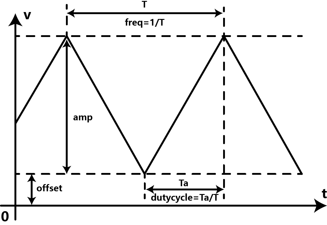
- The user can modify the parameter in DAC.outputTriangle () to change the amplitude, frequency, DC offset and duty cycle of the triangular wave.
/*
 * file OutputVoltage.ino
 *
 * @ https://github.com/DFRobot/DFRobot_MCP4725
 *
 * connect MCP4725 I2C interface with your board (please reference board compatibility)
 *
 * Output a constant voltage value and print through the serial port.
 *
 * Copyright   [DFRobot](https://www.dfrobot.com), 2016
 * Copyright   GNU Lesser General Public License
 *
 * version  V1.0
 * date  2018-1-25
 */
#include "DFRobot_MCP4725.h"
#define  REF_VOLTAGE    5000

DFRobot_MCP4725 DAC;

void setup(void) {
  Serial.begin(115200);
  /* MCP4725A0_address is 0x60 or 0x61
   * MCP4725A0_IIC_Address0 -->0x60
   * MCP4725A0_IIC_Address1 -->0x61
   */
  DAC.init(MCP4725A0_IIC_Address0, REF_VOLTAGE);
}

void loop(void) {
  /*Output amplitude 5000mv, frequency 10HZ,
   *the rise of the entire cycle accounted for 50% of the DC offset 0mv triangular wave.
   */
  DAC.outputTriangle(5000,10,0,50);
}
Results
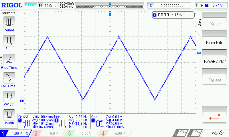
- A full triangular wave of 5V (peak-to-peak), 10Hz, duty cycle of 50% without DC bias can be observed
void outputTriangle(uint16_t amp, uint16_t freq, uint16_t offset, uint8_t dutyCycle)
- function description:generate a triangle wave Vo. When Vo>REF_VOLTAGE, Vo=REF_VOLTAGE; When Vo<0, Vo=0.
- amp: unit in mV. Set the amplitude of the triangle (sawtooth) wave. Value ranges 0 ~ REF_VOLTAGE. When this value is larger than REF_VOLTAGE, amp=REF_VOLTAGE.
- freq: unit in Hz. Set the frequency of the triangle (sawtooth) wave. Value ranges 0 ~ 100. When this value is larger than 100, freq=100; When this value takes 0, the module outputs a constant 0V.
- offset: unit in mV. Set the DC offset of the triangle (sawtooth) wave. Value ranges 0 ~ REF_VOLTAGE. When this value is larger than REF_VOLTAGE, offset=REF_VOLTAGE.
- dutyCycle: unit in percentage (%). Set the duty cycle of the triangle (sawtooth) wave. This value ranges 0 ~ 100. When dutyCycle equals 0 or 100, it becomes a sawtooth wave.
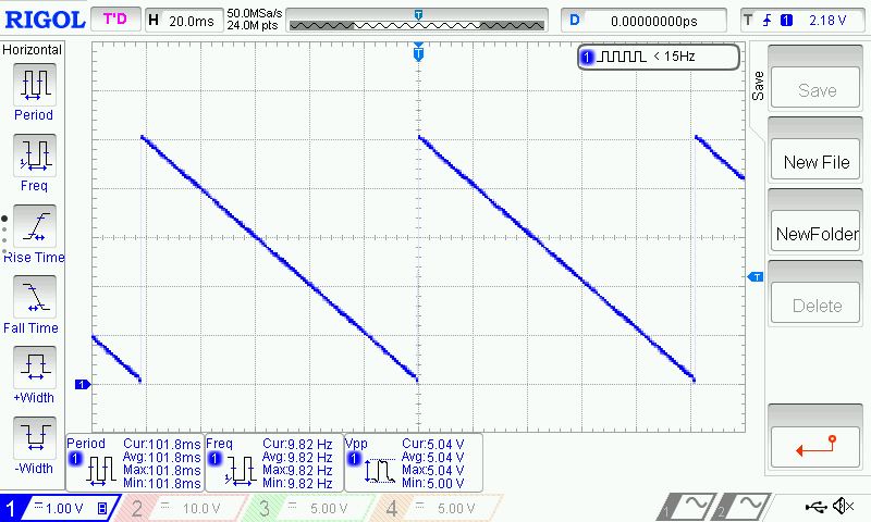
- Change the dutyCycle to 0 while the other parameters remain the same. That is "DAC.outputTriangle (5000,10,0,0)", which can generate a 10Hz sawtooth wave of 5V in amplitude.
Raspberry Pi Tutorial
Requirements
- Hardware
- Raspberry Pi 3 Model B (or similar) x 1
- DFRobot Gravity: 12-Bit I2C DAC Module x 1
- Gravity 4-pin sensor wire (or Dupont wires) x 1
- Digital multimeter (optional) x 1
- Oscilloscope (optional) x 1
- Software
- Download and install the Gravity 12-Bit I2C DAC RaspberryPi library
- RASPBIAN
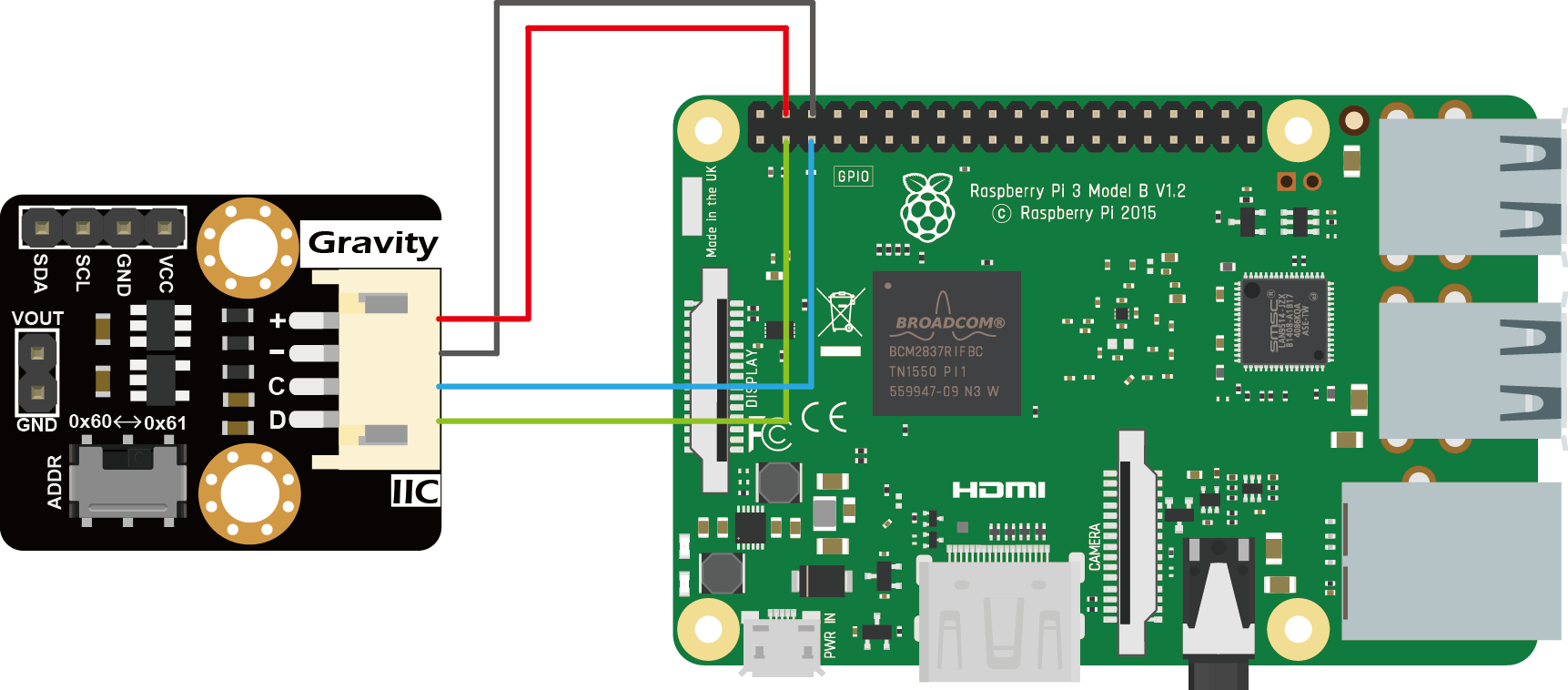
Connection Diagram
Installation
1.Start the I2C interface of the Raspberry Pi. If it is already open, skip this step. Open Terminal, type the following command, and press Enter:
pi@raspberrypi:~ $ sudo raspi-config
Then use the up and down keys to select “5 Interfacing Options” -> “P5 I2C” and press Enter to confirm “YES”. Reboot the Raspberry Pi.
2.Installing Python libraries and git (networking required). If it is already installed, skip this step. In the Terminal, type the following commands, and press Enter:
pi@raspberrypi:~ $ sudo apt-get update
pi@raspberrypi:~ $ sudo apt-get install build-essential python-dev python-smbus git
3.Download the driver library and run it.In the Terminal, type the following commands, and press Enter:
pi@raspberrypi:~ $ git clone https://github.com/DFRobot/DFRobot_MCP4725.git
pi@raspberrypi:~ $ cd /home/pi/DFRobot_MCP4725/RaspberryPi/python
pi@raspberrypi:~/DFRobot_MCP4725/RaspbeeryPi/python $ sudo python DFRobot_MCP4725.py
Calibration and Adjustable Analog Voltage Output
Users are required an additional high-precision digital multimeter to complete the calibration, the specific steps are as follows:
-
Connect the module to the Raspberry Pi according to the connection diagram above and set I2C address to 0x60 by ADDR switch on the module. If I2C address 0x61 is preferred, you need to modify the parameter of the function mcp4725.setAddr_MCP4725() to MCP4725A0_IIC_Address1.
-
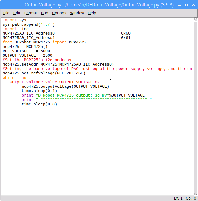
Open Python codes OutputVoltage.py and change both REF_VOLTAGE and OUTPUT_VOLTAGE to 5000 (if the module uses 3.3V, change to 3300).
-
In the Terminal, type in the following commands and press Enter to run the sample code:
 pi@raspberrypi:~/DFRobot_MCP4725/RaspbeeryPi/python $ cd OutputVoltage
 pi@raspberrypi:~/DFRobot_MCP4725/RaspbeeryPi/python/OutputVoltage $ sudo python OutputVoltage.py
-
Use the multimeter to measure the output voltage of VOUT and change the value of REF_VOLTAGE accordingly. For example, VOUT = 4950mV, the "#define REF_VOLTAGE 5000" should be revised to "REF_VOLTAGE 4950". Calibration completed.
-
Change the value of OUTPUT_VOLTAGE (unit in mV) to your desired analog output voltage. This value should be smaller than REF_VOLTAGE or the maximum output voltage will be limited to REF_VOLTAGE. Before using the sample code below, write the calibration value to REF_VOLTAGE first to get a more accurate output voltage.
-
There are two ways to open and modify Python programs:
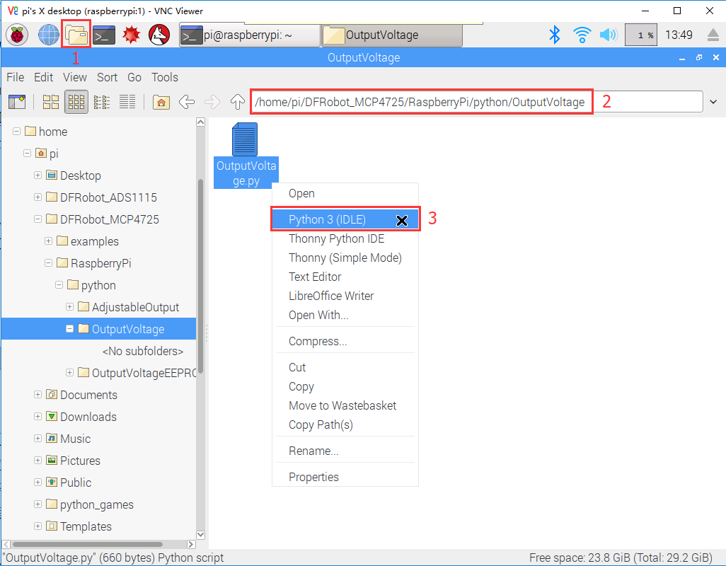
1.Use the IDLE integrated development environment to modify Python programs in a graphical environment. Click "File Manager" in the menu bar, and then type the following address in the address bar
/home/pi/DFRobot_MCP4725/RaspberryPi/Python/OutputVoltage
Right click on the Python source code "OutputVoltage.py" in the directory. Select “Python 3 (IDLE)” from the menu and edit the Python program in the pop-up window. After editing, use the shortcut “Ctrl S” to save and closed window.
2.Use the nano editor to modify Python programs in the Terminal. In the Terminal, enter the following commands:
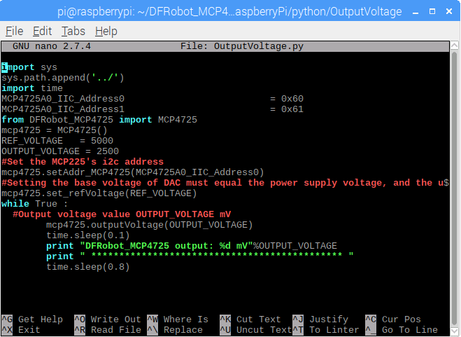
pi@raspberrypi:~/DFRobot_MCP4725/RaspbeeryPi/python/OutputVoltage $ nano OutputVoltage.py
After entering the commands, a Python program is opened using the nano editor. After completing the code modification, use the shortcut “Ctrl O” to save, press Enter to confirm, and then use the shortcut “Ctrl X” to close the nano editor.
Store the DAC Value in EEPROM
-
Connect the module to the Raspberry Pi according to the connection diagram above and set I2C address to 0x60 by ADDR switch on the module. If I2C address 0x61 is preferred, you need to modify the parameter of the function mcp4725.setAddr_MCP4725() to MCP4725A0_IIC_Address1.
-
The user can modify the OUTPUT_VOLTAGE in the OutputVoltageEEPROM.py to change the output value of the analog voltage. REF_VOLTAGE can be changed according to the calibration section. If no calibration is done, enter 5000 (5V) or 3300 (3.3V) depending on the VCC power supply.
-
In the Terminal, type in the following commands and press Enter to run the sample code:
pi@raspberrypi:~ $ cd ~/DFRobot_MCP4725/RaspberryPi/Python/OutputVoltageEEPROM
pi@raspberrypi:~/DFRobot_MCP4725/RaspbeeryPi/python/OutputVoltageEEPROM $ sudo python OutputVoltageEEPROM.py
Results
- A 1V voltage signal can be measured at VOUT. Disconnect the module from the Raspberry Pi. Repower the module, by connecting only the VCC and GND pins of the module to 5V and GND on the Raspberry Pi, respectively. A 1V can still be read at VOUT. The function mcp4725.outputVoltageEEPROM() stores the DAC value in the EEPROM while it outputs a specified analog voltage signal. The module recalls the DAC value in the EEPROM upon power-up and restores the analog output at VOUT.
Generate a Sine Wave
-
Connect the module to the Raspberry Pi according to the connection diagram above and set I2C address to 0x60 by ADDR switch on the module. If I2C address 0x61 is preferred, you need to modify the parameter of the function mcp4725.setAddr_MCP4725() to MCP4725A0_IIC_Address1.
-
REF_VOLTAGE can be changed according to the calibration section. If no calibration is done, enter 5000 (5V) or 3300 (3.3V) depending on the VCC power supply.
-
In the Terminal, type in the following commands and press Enter to run the sample code:
pi@raspberrypi:~ $ cd ~/DFRobot_MCP4725/RaspberryPi/Python/OutputSin
pi@raspberrypi:~/DFRobot_MCP4725/RaspbeeryPi/python/OutputSin $ sudo python OutputSin.py
-
Use an oscilloscope to observe the VOUT output voltage waveform.
-
The user can modify the parameters in the function mcp4725.outputSin() to change the amplitude, frequency and DC offset of the sine wave.
Results
- A full sine wave of 2.5V in amplitude (5V peak to peak), 10Hz and 2.5V DC bias can be observed.

outputSin(amp,freq,offset)
- Function description: Generate a Vo=Voffset Vp*sin(2*pi*f*t) sine waveform. When Vo>REF_VOLTAGE, Vo=REF_VOLTAGE; When Vo<0, Vo=0.
- amp: unit in mV. Set the amplitude Vp of the sine wave. The value range 0 ~ REF_VOLTAGE. When this value is larger than REF_VOLTAGE, amp=REF_VOLTAGE. When amp is set to 0, the function return a DC signal with amplitude determined by offset.
- freq: unit in Hz. Set the frequency of the sine wave . The value ranges 0 ~ 40. When this value is larger than 40, it takes 100; when it is equal to 0, the function returns a DC signal.
- offset: unit in mV. Set the DC offset Voffset of the sine wave. The value ranges 0 ~ REF_VOLTAGE. When this value is larger than REF_VOLTAGE, amp=REF_VOLTAGE.

Generate a Triangle Wave
-
Connect the module to the Raspberry Pi according to the connection diagram above and set I2C address to 0x60 by ADDR switch on the module. If I2C address 0x61 is preferred, you need to modify the parameter of the function mcp4725.setAddr_MCP4725() to MCP4725A0_IIC_Address1.
-
REF_VOLTAGE can be changed according to the calibration section. If no calibration is done, enter 5000 (5V) or 3300 (3.3V) depending on the VCC power supply.
-
In the Terminal, type in the following commands and press Enter to run the sample code:
pi@raspberrypi:~ $ cd ~/DFRobot_MCP4725/RaspberryPi/Python/OutputTriangle
pi@raspberrypi:~/DFRobot_MCP4725/RaspbeeryPi/python/OutputTriangle $ sudo python OutputTriangle.py
-
Use an oscilloscope to observe the VOUT output voltage waveform.
-
The user can modify the parameters in the function mcp4725.outputTriangle() to change the amplitude, frequency, DC offset and duty cycle of the Triangle wave.
Results
- A full triangular wave of 5V (peak-to-peak), 10Hz, duty cycle of 50% without DC bias can be observed.

outputTriangle(amp,freq,offset,dutyCycle)
- function description:Generate a triangle wave Vo. When Vo>REF_VOLTAGE, Vo=REF_VOLTAGE; When Vo<0, Vo=0.
- amp: unit in mV. Set the amplitude of the triangle (sawtooth) wave. Value ranges 0 ~ REF_VOLTAGE. When this value is larger than REF_VOLTAGE, amp=REF_VOLTAGE.
- freq: unit in Hz. Set the frequency of the triangle (sawtooth) wave. Value ranges 0 ~ 40. When this value is larger than 40, freq=40; When this value takes 0, the module outputs a constant 0V.
- offset: unit in mV. Set the DC offset of the triangle (sawtooth) wave. Value ranges 0 ~ REF_VOLTAGE. When this value is larger than REF_VOLTAGE, offset=REF_VOLTAGE.
- dutyCycle: unit in percentage (%). Set the duty cycle of the triangle (sawtooth) wave. This value ranges 0 ~ 100. When dutyCycle equals 0 or 100, it becomes a sawtooth wave.

- Change the dutyCycle to 0 while the other parameters remain unchanged. That is "DAC.outputTriangle (5000,10,0,0)", which can generate a sawtooth wave of 5V in amplitude and 10Hz.

FAQ
-
Q1. Why the highest frequency of the waveform provided by the MCP4725 library is only as high as 100Hz? Is it possible the frequency can be set higher?
A. The MCP4725 uses I2C to communicate with the controller. When using traditional controllers such as the Arduino, the fastest mode, Fast (400kbps), can only be used. Under such transfer speed, DAC module can barely reached 100 Hz. The MCP4725's I2C supports high-speed mode, High-speed (3.4Mbps), but most of the mainstream controllers does not support this I2C mode. In sum, limited by the communication interface, the output frequency is difficult to be further improved.
For more questions, advice or cool ideas to share, please visit the DFRobot Forum.
More Documents
FAQ
For any questions, advice or cool ideas to share, please visit the DFRobot Forum.
