Introduction
An OLED display works without a backlight. Thus, it can display deep black levels and can be thinner and lighter than a liquid crystal display (LCD). In low ambient light conditions such as a dark room an OLED screen can achieve a higher contrast ratio than an LCD. OLED technology is used in commercial applications such as displays for mobile phones and portable digital media players, car radios and digital cameras among others.
Support arduino controller and .NET Gadgeteer-compatible mainboard
Specification
- Working Voltage:3.3V,5V
- 262,144 Colors(max)
- 128×128 RGB pixel resolution
- Interface:SPI or Gadgeteer
- temperature:-30℃ ~ +70℃
- OLED Size:26.855 × 26.864(mm)
- Module Size:52.00 × 42.00(mm)
- Weight:20 g
- Size:1.5 inch
- Driver IC:SSD1351
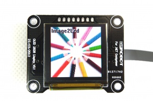
Board Overview

Pins Identification
Arduino port:
1、3.3:Logic power3.3V
2、5V:OLED power 5V (through boost circuit to supply 13V to screen)
3、G:GND
4、RST:reset
5、SCK:SCK
6、SI:MOSI
7、CS:Chip Select
8、DC:D/C
*Gadgeteer port:
PIN1:3.3V
PIN2:5V
PIN3:NC
PIN4:RST
PIN5:DC
PIN6:CS
PIN7:SI
PIN8:NC
PIN9:SCK
PIN10:G
SPI Sequence Diagram

Commands List
The address of rows and columns and the display mode can be changed by setting command. For more detail refer to SSD1351.pdf page 32~46.
We will simply explain these above-mentioned commands through the example Set Re-map / Color Depth (Display RAM to Panel) in Page 32 :
A[7:6] Set Color Depth
00b 256 color
01b 65K color,[reset]
10b 262k color, 8/18-bit,16 bit (1stoption) MCU interface
11b 262k color, 16 - bit MCU interface (2ndoption)
With different mode, there are different bits for each pixel data as you can see below (refer to SSD1351.pdf Page 21,22)
For example: if written A[7:6]=01b to choose 65K color mode,we use 2 8-bit data to determine a pixel in which C0~C4 represents R、B0~B5 represents G,A0~A4 represents B.

A[2] Set Color Sequence
A[2]=0b, Color sequence: A-B-C [reset]
A[2]=1b, Color sequence is swapped: C-B-A
So , in depth 65k color with sequence C-B-A(RGB) mode , we can write data 0xf8,0x00 to make the screen red; and in sequence A-B-C(BGR) with same depth ,write 0x00,0x1f to make screen red.
Tutorial
Requirements
-
Hardware
- DFRduino UNO R3 (or similar) x 1
- OLED 2828 Display Module x 1
- M-M/F-M/F-F Jumper wires
-
Software
Connecting Diagram
Board ———— uno
3.3 ———— 3.3V
5V ———— 5V
G ———— GND
RST ———— D7
SCK ———— D13
SI ———— D11
CS ———— D8
DC ———— D9
Sample Code
#include "U8glib.h"
U8GLIB_SSD1351_128X128_332 u8g(13, 11, 8, 9, 7); // Arduino UNO: SW SPI Com: SCK = 13, MOSI = 11, CS = 8, DC = 9, RESET = 7 (http://electronics.ilsoft.co.uk/ArduinoShield.aspx)

void draw(void) {
  // graphic commands to redraw the complete screen should be placed here
  u8g.setFont(u8g_font_unifont);
  //u8g.setFont(u8g_font_osb21);
  u8g.drawStr( 0, 22, "Hello World!");
}

void setup(void) {

  // flip screen, if required
  // u8g.setRot180();

  // set SPI backup if required
  //u8g.setHardwareBackup(u8g_backup_avr_spi);

  // assign default color value
  if ( u8g.getMode() == U8G_MODE_R3G3B2 ) {
    u8g.setColorIndex(255);     // white
  }
  else if ( u8g.getMode() == U8G_MODE_GRAY2BIT ) {
    u8g.setColorIndex(3);         // max intensity
  }
  else if ( u8g.getMode() == U8G_MODE_BW ) {
    u8g.setColorIndex(1);         // pixel on
  }
  else if ( u8g.getMode() == U8G_MODE_HICOLOR ) {
    u8g.setHiColorByRGB(255,255,255);
  }
}

void loop(void) {
  // picture loop
  u8g.firstPage();
  do {
    draw();
  } while( u8g.nextPage() );

  // rebuild the picture after some delay
  delay(500);
}
FAQ
| Q&A | Some general Arduino Problems/FAQ/Tips |
|---|---|
| A | For any questions, advice or cool ideas to share, please visit the DFRobot Forum. |