Gravity: Analog EMG Sensor
SKU: SEN0240
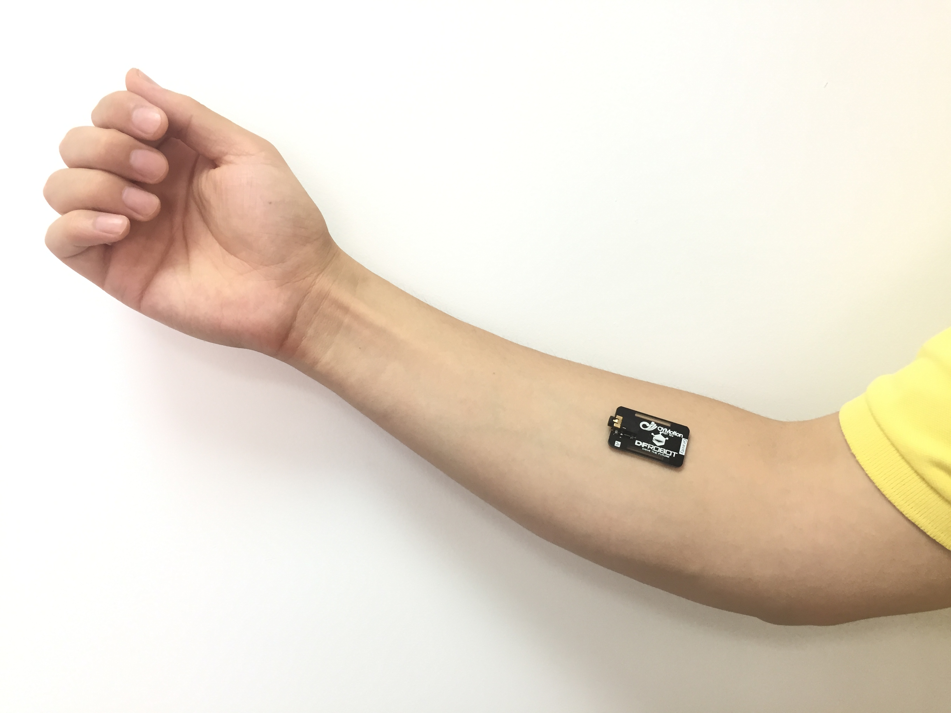
Gravity: Analog EMG Sensor(by DFRobot and OYMotion) offers a noninvasive method to detect muscle and neural activities through sEMG, featuring integrated filtering and amplification circuits. Its output is analog, based on a 1.5V reference voltage, and ranges from 0 to 3.0V. The sensor is compatible with Arduino, allowing users to analyze muscle tension and strength. Easy to use with dry electrodes, it is ideal for both static and dynamic applications, offering a longer lifespan compared to traditional medical electrodes. The sensor is suitable for various human-computer interaction applications, expanding beyond traditional medical uses.