Introduction
Having troubles with inadequate digital I/O when using Arduino with robots or interactive media? This IIC to GPIO shield helps you solve the problem, Arduino has only two data lines (SCL-Analog PIN5, SDA-Analog PIN4) and IIC can transfer I / O module communication, to convert the 16 digital IO ports, read-write. 8 simultaneous parallel modules, each module can be set to address.
Specification
- Module power supply: +5 V
- 16 Digital I/O port comes with internal pull-up
- Can be set to eight addresses (address range of 0x20 ~ 0x27)
- 8 modules simultaneously in parallel (IIC bus need to pull together)
- Module Size: 56x53mm (2.21x2.08 in)
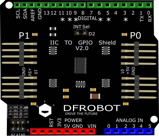
Board Overview

Plug = 0
Unplug = 1
| A2 | A1 | A0 | IIC Address |
|---|---|---|---|
| 0 | 0 | 0 | 0x20 (Default) |
| 0 | 0 | 1 | 0x21 |
| 0 | 1 | 0 | 0x22 |
| 0 | 1 | 1 | 0x23 |
| 1 | 0 | 0 | 0x24 |
| 1 | 0 | 1 | 0x25 |
| 1 | 1 | 1 | 0x26 |
| 1 | 1 | 1 | 0x27 |
Tutorial
Requirements
-
Hardware
-
Software
- Arduino IDE V1.6.5 Click to Download Arduino IDE from Arduino®
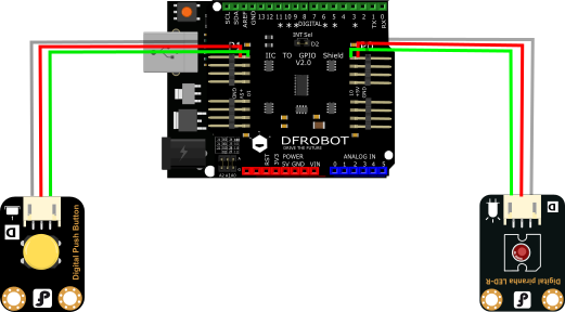
Connection Diagram

Sample Code
In this section, we will use an Arduino library written by nicoverduin
Github Library. About Library installation.
#if defined(ARDUINO) && ARDUINO >= 100
#include "Arduino.h"
#else
#include "WProgram.h"
#endif

#include "clsPCA9555.h"
#include "Wire.h"


PCA9555 ioport(0x20);

void setup()
{
  ioport.pinMode(7, OUTPUT); //Set GPIOs pinMode LED
  ioport.pinMode(8, INPUT);  //Button
}

void loop()
{
  if (ioport.digitalRead(ED8) == LOW) {
    ioport.digitalWrite(7, LOW);                  //Turn off Led
  }

  if (ioport.digitalRead(ED8) == HIGH) {
    ioport.digitalWrite(7, HIGH);                 //Turn on Led
  }

}
Library Explanation
Library Functions
- pinMode() same as standard Arduino
- digitalRead() same as Arduino
- digitalWrite() same as Arduino
Pin map
P0.0~P0.7 map to GPIO 0 ~ 7 or ED0 - ED7
P1.0~P1.7 map to GPIO 8 ~ 15 or ED8 - ED15
FAQ
There are no questions about this product yet. If you have any problems or suggestions, you are welcome to email us or post on the DFRobot forum!
| For any questions/advice/cool ideas to share, please visit the DFRobot Forum. |
|---|
More Documents
history wiki page V1.0
datasheet.pdf PCA9555 datasheet
Schematic V2.0
Layout V2.0
svg files
