Introduction
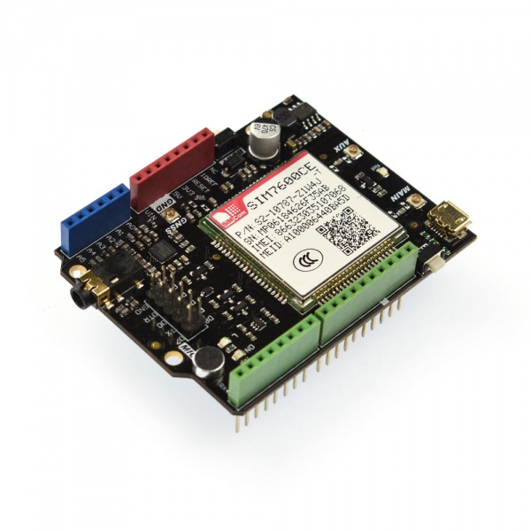
SIM7600CE-T 4G(LTE) Shield is an Arduino expansion Board based on 4G/3G/2G communication and GNSS positioning technology, small as a credit card and compatible with controller boards like Arduino UNO, Leonardo and Mega. It accords with standard Arduino interface.
SIM7600CE-T is a complete multi-band LTE-TDD/ LTE-FDD/HSPA+/TD-SCDMA/EVDO and GSM/GPRS/EDGE module solution which supports LTE CAT4 up to 150Mbps for downlink and 50Mbps for uplink data transfer.
With stable performance, this small cost-effective expansion shield can realize SMS and data transmission in a pretty low power consumption. Besides, it adopts the latest SIM7600CE module. Compared with other GSM/GPRS/GPS modules on the market, this module is well advanced in stable performance and powerful function such as 4G communication and accurate GNSS positioning.
Specification
- Operating Voltage: 5V
- Input Power: VIN(7-12V)/USB(5V)
- Support Network:
- TDD-LTE B38/B39/B40/B41
- FDD-LTE B1/B3/B8
- TD-SCDMA B34/B39
- WCDMA/HSDPA/HSPA+ B1/B8
- CDMA 1X/EVDO BC0
- GSM/GPRS/EDGE 900/1800 MHz
- 4G Communication Rate:
- Uplink Rate: 50Mbps
- Downlink Rate: 150Mbps
- Control via AT Commands (3GPP TS 27.007,27.005 and SIM7500_SIM7600 Series_AT Command)
- Support GNSS (Global Navigation Satellite System)
- Support Low-power Consumption Mode: 20mA@7V Flight Mode
- Support LED Status Display: display the power supply status, network connection and operating mode
- Operating Temperature: -40℃~85℃
- Dimension: 6954mm/2.712.13”
Pinout
 NOTE
NOTE
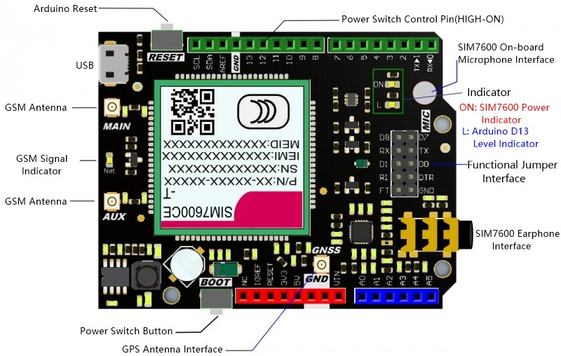
- Occupied Pins: D0, D1, D12. Pin D12 has been connected to the SIM7600CE power switch. You can set the pin HIGH/LOW to turn the module ON/OFF in code.
- SIM7600 on-board MIC shares the same channel with 3.5mm SIM7600CE microphone interface.
- Boot–power switch, short-press 1s to start the module and long-press 3s to shut down it.
- Indicator “ON” –SIM7600CE power indicator. The module will work properly only when it is powered by the external power supply.
- Net–GSM Signal Indicator:
- On: searching for network
- Flash Quickly(1 time per second): network registering is done.
- Jumper Cap Interface:
- RX/TX–SIM7600CE communication serial port, control via AT command.
- D0/D1&D7/D8–select the corresponding interface to communicate with SIM7600CE according to the Arduino controller you used.(For AT test)
- RI–Normally RI will keep high level until certain conditions such as receiving SMS, or a URC report coming, and then it will change to low level. It will stay low until the host controller clears the interrupted event with “AT+CRIRS” AT command.
- DTR–DTR pin can be used to wake SIM7600CE from sleep. When SIM7600CE enters sleep mode, pulling down DTR can wake SIM7600CE.
- FT–Low Level: Flight mode; High Level: Normal mode
Function Debug (AT Command)
In the following section, we will provide a demo to show you how to send AT command via serial port so as to debug SIM7600CE-T shield. For more AT commands and instructions, please refer to AT Command Set at the end of this page.
Preparation
- Hardware
- Arduino UNO ×1
- SIM7600CE-T Shield ×1
- External Power Supply ×1
- Software
- Arduino IDE(the newest version), click to download Arduino IDE
- Serial Debugger(choose the device that can send hexadecimal data)
Steps
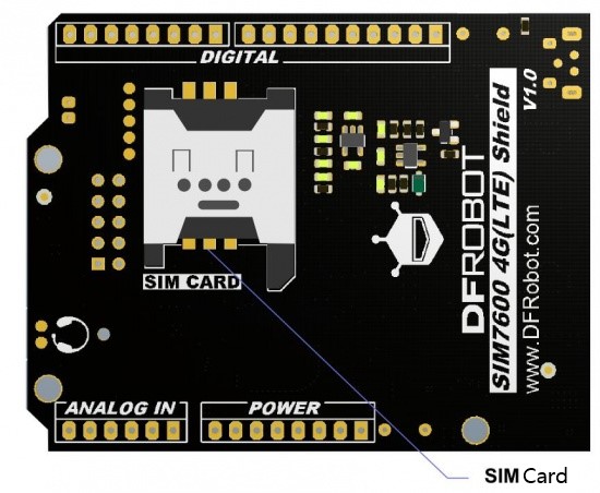
- Insert SIM card into SIM7600CE-T shield, then connect it with Arduino UNO and plug in the external power supply.
- Press “Boot” to start the module, and wait for SIM card to be successfully registered into Network, which means Net indicator begins to flash quickly.
- Select D0/D1 or D7/D8 as communication serial port through jumper cap according to the type of controller board.
- Take Arduino UNO as an example, download the following code to UNO and connect RX-D8/TX-D7 by jumper cap.
#include <SoftwareSerial.h>
SoftwareSerial myserial(7, 8); //Define virtual serial port name as myseria,Rx is port 7, Tx is port 8
void setup()
{
  myserial.begin(115200); //Initialize virtual serial port
  Serial.begin(115200); //Initialize Arduino default serial port
}

void loop()
{
  while(1){
  while (myserial.available()) {
    Serial.write(myserial.read());//if Serial received data, output it via mySerial.
  }
  while(Serial.available()) {
    myserial.write(Serial.read());//if myserial received data, output it via Serial.
  }
}
}
Make a Call
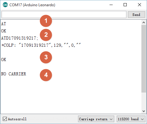
Please choose the board and serial port for the main board, then open your Arduino Serial Monitor, and choose Baud Rate@ 115200, Format@ Carriage Return, you can also use other software or even wireless module.
-
Send AT to enter AT mode, you will get OK, or please check the serial monitor setting or if the NET led is flashing every 3 seconds.
-
Send ATD170****9217; to make a call, do not forget the ";" in the end;
-
If accepted, you will see OK.
-
If rejected, you will see NO CARRIER.
Answer/Reject an Incoming Call
-
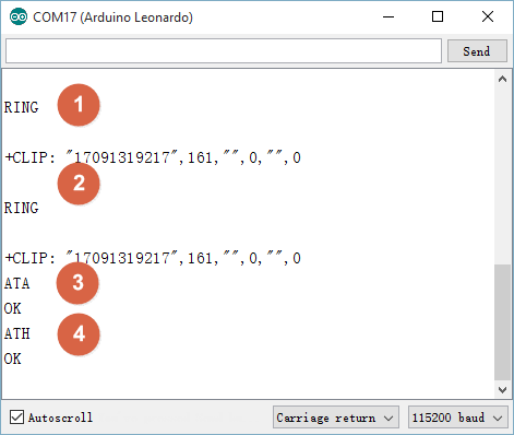
If there is an incoming call, serial port 1 will receive the message
-
The number can be displayed if your SIM card has this function
-
Send ATA to answer the call
-
Send ATH to reject the call
Send a Message
We recommend using DF Serial Debugger because when you are going to send the message, you have to send 0x1A in HEX. The DF Serial Debugger can send data in HEX while the Arduino IDE can't.
| NOTE: Do NOT tick the checkbox hex until Step 4 which is to send 0x1A in HEX. |
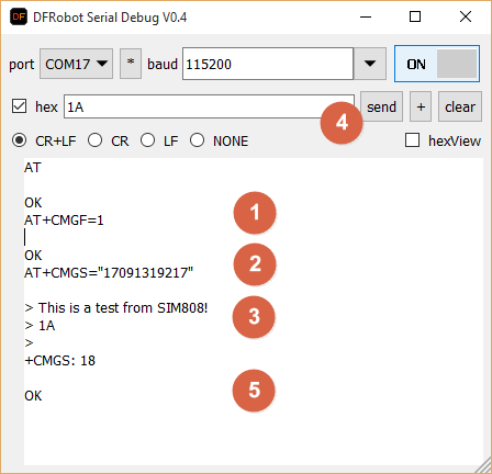
- Open DF Serial Debugger and copy the settings according to the image below. If you cannot open the port, please check if the port is occupied by the Arduino IDE serial monitor.
- Send AT+CMGF=1 to set the SMS in text format. You will get OK
- Send AT+CMGS="170****9217" to set the receiver number. You will see a notation >
- Write the content of the message
- Send 1A(HEX) as an end to send the message
- You will get OK, and the message will be sent
:
Read a Message
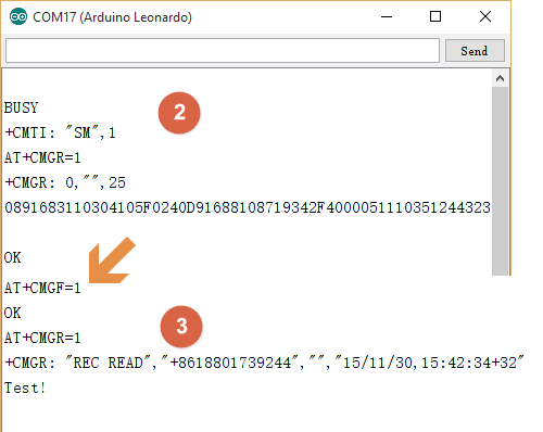
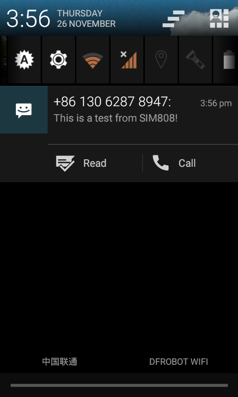
- Send a message to the SIM card on the module, I sent test! here
- The serial monitor will print a message +SMTI: "SM",1, and 1 shows the number of the message
- Send AT+CMGR=1 to read the message of 1. The message "Test!" should display
| NOTE: If the text is unreadable, please set the message in TEXT by AT+CMGF=1. |
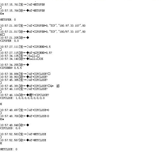
TCP Communication
GPS Data Output
Note: in order to get stable GPS data, please place the GPS antenna outside.
- Send AT+CGPS=1 command (turn on GPS)
- Send AT+CGPSINFO command (read GPS data)
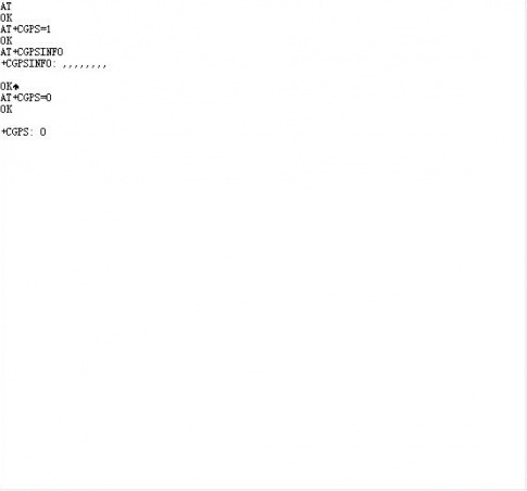
- If the GPS antenna has been placed in open area and GPS data has been received, wait for few minutes, the accurate GPS position data will be output.
- Send AT+CGPS=0 command to turn off GPS.
- Send AT+CPOF to shut down the module.
For more details please refer to the AT instruction manual(Bottom of this page>”More”)
SIM7600CE-T Power Save Mode
Minimum Functionality Mode
Minimum functionality mode means to reduce the module’s functions to least so as to minimize the current consumption. Use “AT+CFUN=
- AT+CFUN=0: Minimum Functionality Mode. Under this mode, serial port can still be used, but the RF and SIM card function and part of the AT commands will be disabled.
- AT+CFUN=1: Full Functionality Mode. (default)
- AT+CFUN=4: Flight Mode. Under this mode, serial port can still be used, but RF function and part of AT commands will not be accessible.
FAQ
| Q&A | Some general Arduino Problems/FAQ/Tips |
|---|---|
| A | For any questions, advice or cool ideas to share, please visit the DFRobot Forum. |
| Q&A | Encountering I2C address conflicts? |
| A | For a comprehensive guide on identifying and resolving I2C address conflicts in embedded systems, check out this detailed article: How to Resolve I2C Address Conflicts. It covers practical hardware and software solutions to ensure smooth communication in your IoT devices. |

