Introduction
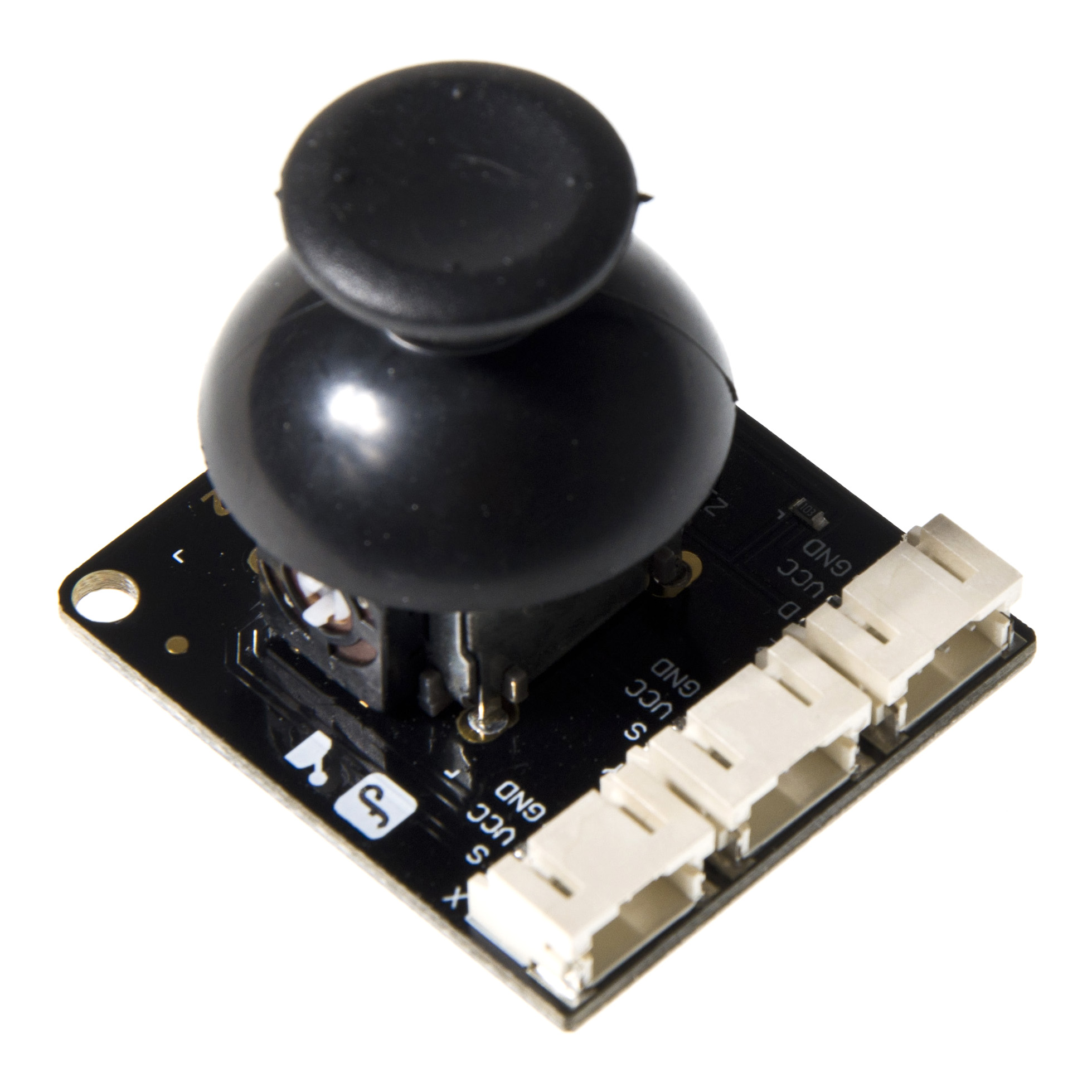
Lots of robot projects need joystick. This joystick module for arduino provides a affordable solution to that. Simply connect to two analog inputs, the robot is at your commands with X,Y control. It also has a switch that is connected to a digital pin. This joystick module can be easily connect to Arduino by IO Expansion Shield For Arduino(V5) (SKU: DFR0088) with supplied cables.
Specification
- Supply Voltage: 3.3V to 5V
- Interface: Analog x2,Digital x1
- Gravity PH2.0 Interface
- Size: 39 x 35 x 30mm
- Weight: 15g
Board Overview

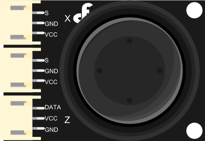
| Pin X |
|---|
| S - Analog OUT |
| Pin Y |
| S - Analog OUT |
| Pin Z |
| D - Digital OUT |
Tutorial
Requirements
-
Hardware
- DFRduino UNO R3 (or similar) x 1
- Joystick Module V2 x 1
- M-M/F-M/F-F Jumper wires
-
Software
Connection Diagram

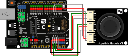
| Wiring Instructions |
|---|
| Pin X |
| S - A1 |
| Pin Y |
| S - A0 |
| Pin Z |
| D - D3 |
Sample Code
// #
// # Editor     : Lauren from DFRobot
// # Date       : 17.01.2012

// # Product name: Joystick Module
// # Product SKU : DFR0061
// # Version     : 1.0

// # Description:
// # Modify the Sample code for the Joystick Module

// # Connection:
// #        X-Axis  -> Analog pin 0
// #        Y-Axis  -> Analog pin 1
// #        Z-Axis  -> Digital pin 3
// #


int JoyStick_X = 0; //x
int JoyStick_Y = 1; //y
int JoyStick_Z = 3; //key

void setup()
{
  pinMode(JoyStick_Z, INPUT);
  Serial.begin(9600); // 9600 bps
}
void loop()
{
  int x,y,z;
  x=analogRead(JoyStick_X);
  y=analogRead(JoyStick_Y);
  z=digitalRead(JoyStick_Z);
  Serial.print(x ,DEC);
  Serial.print(",");
  Serial.print(y ,DEC);
  Serial.print(",");
  Serial.println(z ,DEC);
  delay(100);
}
