Introduction
Say goodbye to messy cables! This IO shield is a powerful expansion shield for the Bluno M3. The breakouts for digital pins range from D0 to D38, including 5 UARTS, 8 PWM pins and 8 analog pins. The IO Expansion shield uses a convenient color coded 3 pin format for signal, voltage and ground that is useful if used with a large range of devices. The IO expansion shield also integrates an external power connector for servos - if you need to power a large array of servos, use the screw terminals to connect your power supply and drive them directly from your Bluno M3. It will switch to the right power source automatically. An intelligent power regulator allows you to connect a battery and USB cable simultaneously, and an on-board voltage switch makes it easy to change the output voltage, making 3.3V or 5V sensors compatible.
Specification
- Interface:
- 39 GPIO pins with color-coded headers
- 8 PWM pins
- 8 Analog Input pins
- 5 UARTS
- 1 I2C/IIC
- 1 SPI
- External power connector for servos
- 3.3V/5V power switch
- Dimensions: 69mm * 54mm
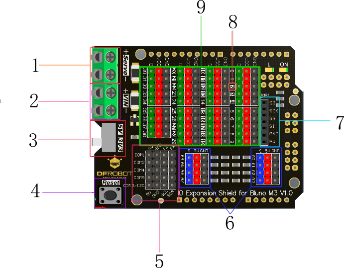
Board Overview

| Num. | Name | Description |
|---|---|---|
| 1 | Servo Power Port | 5-12V |
| 2 | External Power Port | 7-12V |
| 3 | 3.3V/5V Operating Voltage Switch | Select output voltage |
| 4 | Reset Button | - |
| 5 | UARTS and I2C | - |
| 6 | Analog Input Ports | Black: GND; Red: 5V; Blue: Analog Input pins (0~7) |
| 7 | SPI | - |
| 8 | I/O Voltage Instruction | Silk-Screen: White background: supports 5V; Black background supports 3.3V only |
| 9 | Digital I/O ports | Black: GND; Red: 5V; Green: Digital I/O pins (0~38) |
Interface Reference
5V-supported Pins
There are 17 5V-supported pins on the shield.
- Digital I/O pins with white background support 5V power input
- Digital I/O pins with black background support 3.3V power input only, be careful!
Indicator LED “L”
An on-board LED is connecting D13 digital I/O pin.
Color-coded 3-Pin Interface
Green: Digital Signal Blue: Analog Signal Red: VCC Black: GND There are two rows pin headers beside the signal pin headers. They are arranged in regular sequence as Signal/VCC/GND, which is compatible with sensor pins order. All Red pins and Black pins are linked respectively. ’’’Note: Since there are a lot of 5V signal analog sensors that have an operating voltage that is higher than Bluno's operating voltage, we have added bleeder circuits on the shield analog section. They can convert the voltage signal from 0~5V to 0~3.3V one and protect micro controller.’’’
USART and I2C Interface
The shield provides 5 UARTS and 1 I2C interface. Since COM3 and default I2C interface use the same I/O pins, they can’t work simultaneously. You can redefine the I2C pins to avoid this conflict. Refer to Bluno Me reference manual——I2C
3.3V/5V operating voltage switch
The shield includes a voltage hardware setting through a switch to allow compatibility with a bigger range sensors and modules. It can change the color code VCC pins output voltage to 3.3V or 5V.
External Power port
There is an external power port on the shield, which connecting to the M3 on-board external power port. The input voltage could be 7~12V. And when the board is connected to the USB and External power simultaneously, the power resource will change to the external automatically
Servo power port (5~12V)
Servo power port A external power connector for servos, as in other products of this family. If you need to power a large array of servos, use the screw terminals to connect your power supply and just drive it directly from your M3 Servo power port is only connecting to the color-code pin headers, it won’t power the MCU. When you power the board with USB or external power port, and if you connect a power resource (>5V) to the servo power port, color-code VCC pin headers will get power from Servo power port automatically.
FAQ
There are no questions about this product yet, if you have any problems or suggestions, you are welcome to email us or post on our forum! Thank you!
| If you have any questions or cool ideas to share, please visit DFRobot Forum |
|---|
