Introduction
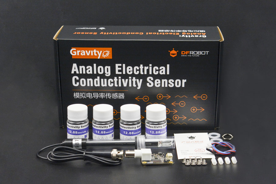
DFRobot Gravity: analog electrical conductivity sensor/meter(K=10) is specially used to measure the high electrical conductivity liquid, such as seawater, concentrated brine, etc. The measurement range is up to 100ms/cm. This product is suitable for the water quality application of mariculture, for example, marine fisheries, marine aquariums.
It supports 3~5v wide voltage input, and is compatible with 5V and 3.3V main control board; The excitation source adopts AC signal, which effectively reduces the polarization effect, improves the precision and prolongs the life of the probe; The software library uses single-point calibration method, and can automatically identify standard buffer solution, so simple and convenient.
With this product, main control board (such as Arduino) and the software library, you can quickly build an electrical conductivity meter, plug and play, no solding required, which providing a set of plug-and-play conductivity measurement solution for makers.
DFRobot provides a variety of water quality sensor products, uniform size and interface, not only meet the needs of various water quality testing, but also suitable for the DIY of multi-parameter water quality tester.
NOTE:
- The probe is a laboratory-grade probe. Do not immerse in liquid for a long time. Otherwise this will shorten the life of the probe.
- Platinum black layer is attached to the surface of the sheet metal in the probe. It should avoid any object touching it. It can only be washed with distilled water, otherwise, the platinum black layer will be damaged, resulting in the inaccurate measurement.
Specification
- Signal Conversion Board
- Supply Voltage: 3.0~5.0V
- Output Voltage: 0~3.2V
- Probe Connector: BNC
- Signal Connector: PH2.0-3Pin
- Measurement Accuracy: ±5% F.S.
- Electrical Conductivity Probe
- Probe Type: Laboratory Grade
- Cell Constant: 10±2
- Support Detection Range: 10~100ms/cm
- Temperature Range: 0~40°C
- Probe Life: >0.5 year (Actual life is related to frequency of use and scene)
- Cable Length: 100±2cm
Board Overview
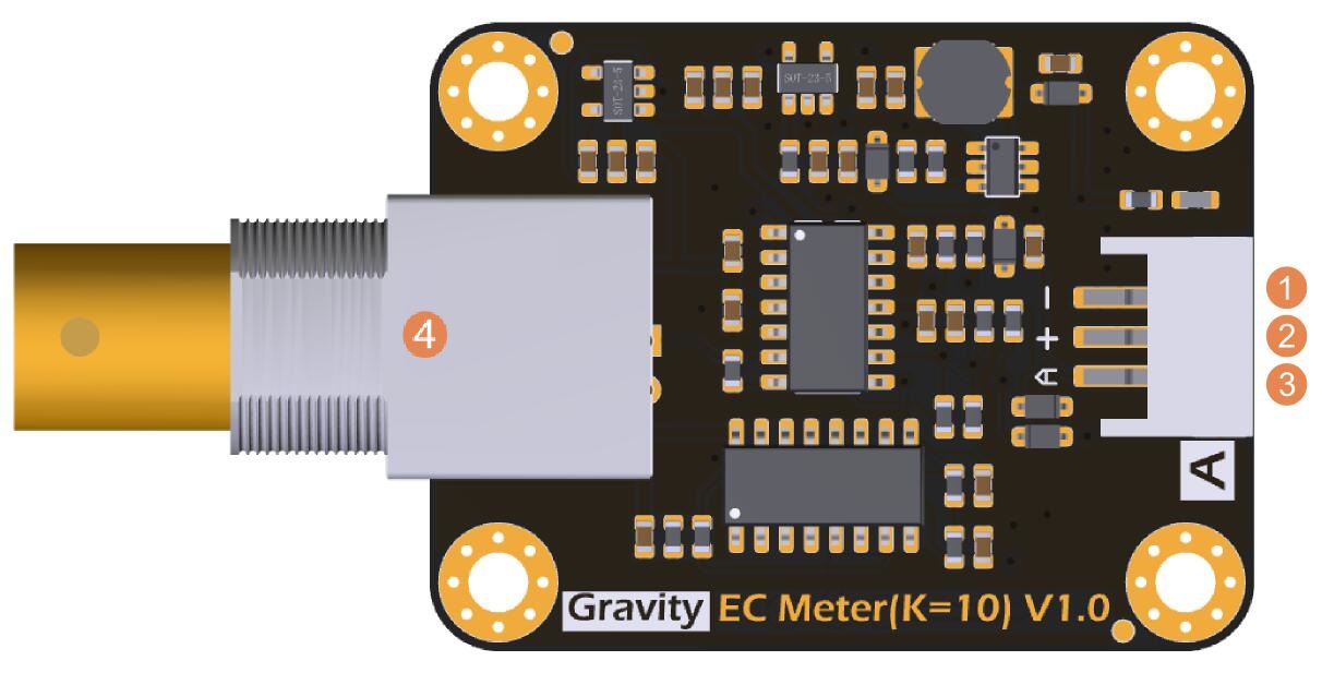
| Num | Label | Description |
|---|---|---|
| 1 | - | Power GND(0V) |
| 2 | + | Power VCC(3.0~5.0V) |
| 3 | A | Analog Signal Output(0~3.2V) |
| 4 | BNC | Probe Connector |
Tutorial
This tutorial will demonstrate how to use this electrical conductivity meter for calibration and measurement. Please read each step carefully.
- In order to ensure the measurement accuracy, it is strongly recommended to add a temperature sensor to measure the temperature and achieve automatic temperature compensation. DS18B20 waterproof temperature sensor can be used.
- Before measuring another liquid, be sure to wash the probe and absorb residual water-drops with paper to prevent contamination of the liquid. You can flush the probe with distilled water.
- An exteranl power supply is recommended for Arduino board to get more accurate and stable reading.
Requirements
-
Hardware
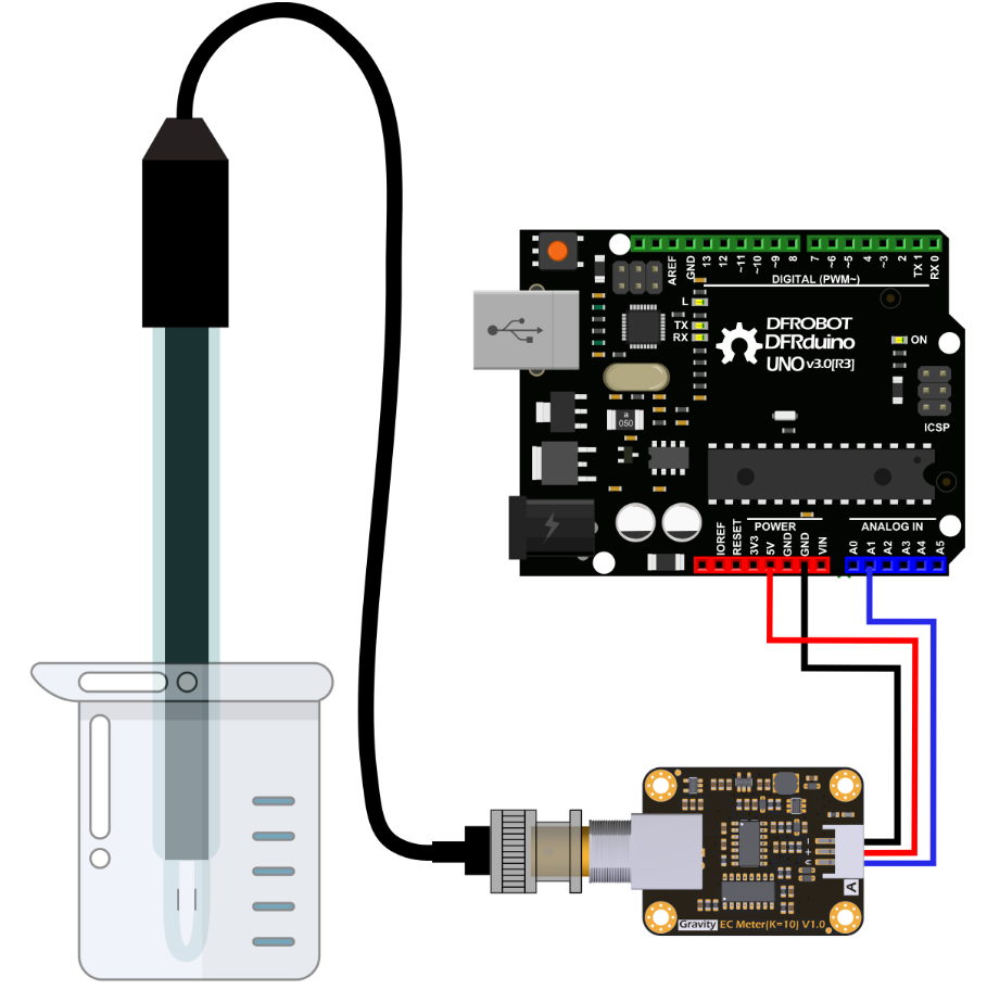
- DFRduino UNO R3 (or similar) x 1
- Analog Electrical Conductivity Meter Board(K=10) x 1
- Electrical Conductivity Probe(K=10) x 1
- Standard Buffer Solution 12.88ms/cm x 1
- Gravity 3pin Sensor Cable (or several DuPont cables) x 1
- Test Solution x1
-
Software
- Arduino IDE(Version requirements: V1.0.x or V1.8.x)
- Download and install the DFRobot_EC10 Library. (About how to install the library?)
Connection Diagram
Calibration
To ensure accuracy, the probe used for the first time, or used for a period of time, needs to be calibrated.
This tutorial uses single-point calibration and therefore requires standard buffer solutions of 12.88ms/cm.
The following tutorial shows how to operate single-point calibration.
- Upload the sample code to the Arduino board, then open the serial monitor, you can see the temperature and electrical conductivity. If you added a temperature sensor, be sure to write the corresponding function code and call it.
- Wash the probe with distilled water, then absorb the residual water-drops with paper. Insert the probe into the 12.88ms/cm standard buffer solution, stir gently, until the values are stable.
- After the values are stable, the single-point can be calibrated. Specific steps are as follows:
- Input ENTEREC command in the serial monitor to enter the calibration mode.
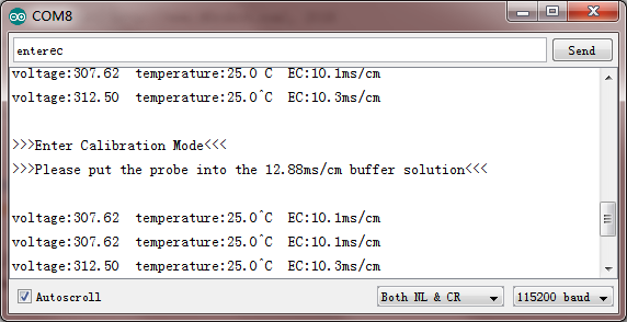
- Input CALEC commands to start the calibration. The program will automatically identify the standard buffer solution of 12.88ms/cm.
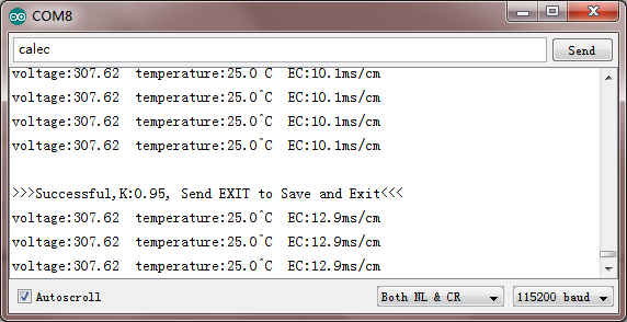
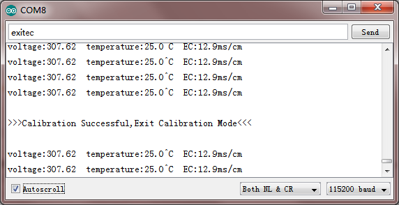
- After the calibration, input EXITEC command to save the relevant parameters and exit the calibration mode.
Note: Only after input EXITEC command in the serial monitor can the relevant parameters be saved.
- Input ENTEREC command in the serial monitor to enter the calibration mode.
- After completing the above steps, the single-point calibration is completed, and then the sensor can be used for actual measurement. The relevant parameters in the calibration process have been saved to the EEPROM of the main control board.
Sample Code
Download and install the DFRobot_EC10 Library. (About how to install the library?)
/*
 * file DFRobot_EC10.ino
 * @ https://github.com/DFRobot/DFRobot_EC10
 *
 * This is the sample code for Gravity: Analog Electrical Conductivity Sensor / Meter Kit(K=10), SKU: DFR0300_H.
 * In order to guarantee precision, a temperature sensor such as DS18B20 is needed, to execute automatic temperature compensation.
 * You can send commands in the serial monitor to execute the calibration.
 * Serial Commands:
 *   enterec -> enter the calibration mode
 *   calec -> calibrate with the standard buffer solution, one buffer solutions(12.88ms/cm) will be automaticlly recognized
 *   exitec -> save the calibrated parameters and exit from calibration mode
 *
 * Copyright   [DFRobot](https://www.dfrobot.com), 2018
 * Copyright   GNU Lesser General Public License
 *
 * version  V1.0
 * date  2018-11
 */

#include "DFRobot_EC10.h"
#include <EEPROM.h>

#define EC_PIN A1
float voltage,ecValue,temperature = 25;
DFRobot_EC10 ec;

void setup()
{
  Serial.begin(115200);
  ec.begin();
}

void loop()
{
    static unsigned long timepoint = millis();
    if(millis()-timepoint>1000U)  //time interval: 1s
    {
      timepoint = millis();
      voltage = analogRead(EC_PIN)/1024.0*5000;  // read the voltage
      Serial.print("voltage:");
      Serial.print(voltage);
      //temperature = readTemperature();  // read your temperature sensor to execute temperature compensation
      ecValue =  ec.readEC(voltage,temperature);  // convert voltage to EC with temperature compensation
      Serial.print("  temperature:");
      Serial.print(temperature,1);
      Serial.print("^C  EC:");
      Serial.print(ecValue,1);
      Serial.println("ms/cm");
    }
    ec.calibration(voltage,temperature);  // calibration process by Serail CMD
}

float readTemperature()
{
  //add your code here to get the temperature from your temperature sensor
}
FAQ
| Q&A | Some general Problems/FAQ/Tips |
|---|---|
| Q | How long does the probe need to be calibrated? |
| A | The calibration interval is determined by the frequency of use. Normally, you can calibrate it once a month. If used frequently, it can be calibrated once a week. When calibrating, fresh standard buffer solution is recommended. |
| Q | How to achieve automatic temperature compensation? |
| A | The temperature compensation algorithm has been integrated in the DFRobot_EC10 library.You only need to transfer the voltage and temperature to float readEC (float voltage, float temperature) at the same time, to obtain the electrical conductivity with temperature compensation. |
| Q | During the first calibration, the calibration always failed. What could be the reason? |
| A | When calibrating, the relevant parameters are stored in the specified position in EEPROM. If other data previously saved in the same position in EEPROM, there may be a conflict, resulting in an inability to calibrate properly. Use the following code to erase the contents in the specified position in EEPROM. Run it once, then upload the sample code again to restart the calibration. |
#include <EEPROM.h>
#define KVALUEADDR 0x0F
void setup(){
    for(byte i = 0;i< 8; i++ ){
      EEPROM.write(KVALUEADDR+i, 0xFF);
    }
}
void loop(){
}
For any questions, advice or cool ideas to share, please visit the DFRobot Forum.
If you have any questions about using this product, please check the FAQ list for that product for a corresponding solution.
