Introduction
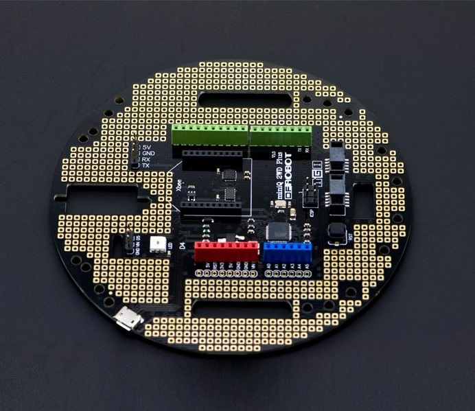
MiniQ 2WD Plus is a control board of MiniQ 2WD arduino robot. It could be fully compatible with the Arduino Leonardo, as well as various expansion shield interface. You can build all kinds of sensor module on it. What is more? It’s unnecessary to use a prototyping board because this board already has a lot of pads, which you youc plug component in. MiniQ 2WD Plus control board can be used as the main controller of desktop robot-car to set up two wheels self-balance robot,.It can also be used as MiniQ 2WD port expansion board, through Gadgeteer interface for communication between two board. That is amazing!
Specification
- Microcontroller: Atmega 32u4
- Accelerometer chip:ADXL345
- Gyroscope chip: ITG3205
- Digital I/O port: total 23(D17 is for RX LED)
- 5V D/A port max allowable current: 40 mA
- Compatible standard Arduino interface
- Supply program download by USB
- 7 PWM channel
- 1 xbee interface(Serial1)
- 1 1-Wire Bus RGB light
- 1 installing hole of 9g servo
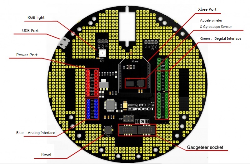
Board Overview

- Power:USB supply or External power supply
- RGB light: integrate driver IC-WS2811,1-Wire Bus control
- D/A input interface:fully compatible with the Arduino Leonardo
- Reset button :more comfortable feel for new microswitch
- 2 Gadgteer interface:connect with all kind of sensor with Gadgteer,also can communication with MiniQ 2WD
- Accelerometer chip:ADXL345
- Gyroscope chip:ITG3205
- Xbee interface:for wireless transfer
- reservation with a installing hole of TowerPro SG90 micro servo
- reservation with UART interface
Tutorial
Acceleration & gyroscope
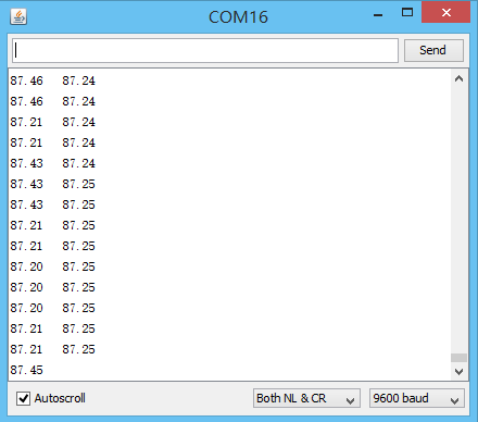
The data which accelerometer & gyroscope read comes through IIC, and output data is compared with the X, Y, and Z axis. If you want the angle to be relative to the coordinate, you need to do the conversion. Of course, because the accelerometers are too sensitive, I believe many of you faced such difficulties that a little shake comes a big fluctuation. There is a simple example as follow for acquiring the relatively stable angle data from gyroscope sensor with angle correction and software filtering. The experiment results can be observed by the serial monitor.

Sample Code
#include <Wire.h>
#include <math.h>
#define DEVICE (0x53)    //ADXL345 device address
#define TO_READ (6)        //num of bytes we are going to read each time (two bytes for each axis)

// Gyroscope Sensor ITG3205
#define ITGAddress   0x68    //set ITG3205 I2C Address(AD0)
#define G_SMPLRT_DIV 0x15    //set register of sampling rate
#define G_DLPF_FS 0x16     // set register of range, low-pass filter band width and clock frequency #define G_INT_CFG 0x17     //set register of interrupt
#define G_PWR_MGM 0x3E    //set register of power management

float xGyro, yGyro, zGyro;      //store angular rate and temperature
int buff[6];                  //store 6 value of X/Y/Z axis with high and low order address  (two bytes for each axis)
byte buff1[6];
//  The offset of gyroscope sensor error correction
int g_offx = -35;
int g_offy = -9;
int g_offz = -30;

void writeRegister(int deviceAddress, byte address, byte val)
{
  Wire.beginTransmission(deviceAddress);
  Wire.write(address);
  Wire.write(val);
  Wire.endTransmission();
}

void readRegister(int deviceAddress, byte address)
{
  Wire.beginTransmission(deviceAddress);
  Wire.write(address);
  Wire.endTransmission();
  Wire.beginTransmission(deviceAddress);
  Wire.requestFrom(deviceAddress, 6);

  int i = 0;
  while(Wire.available())
  { buff[i++] = Wire.read(); }
  Wire.endTransmission();
}

void initGyro()
{
  /*****************************************
 * ITG3205
 * G_SMPLRT_DIV:sampling rate = 125Hz
 * G_DLPF_FS:+ - 2000 rad/s、low pass filter 5HZ、internal sampling rate 1kHz
 * G_INT_CFG:no interrupt
 * G_PWR_MGM:Power management setting: no reset、no sleep mode、no idle mode 、internal oscillator   ******************************************/

  writeRegister(ITGAddress, G_SMPLRT_DIV, 0x07); //set sampling rate
  writeRegister(ITGAddress, G_DLPF_FS, 0x1E); //set  range, low-pass filter band width and internal  sampling rate
  writeRegister(ITGAddress, G_INT_CFG, 0x00); //set  of interrupt (default value )
writeRegister(ITGAddress, G_PWR_MGM, 0x00);    //set power management (default value )

   //Turning on the ADXL345
   writeTo(DEVICE, 0x2D, 0);
   writeTo(DEVICE, 0x2D, 16);
   writeTo(DEVICE, 0x2D, 8);
}

float getGyroValues()
{
  readRegister(ITGAddress, 0x1D); //read gyroscope sensor data
  xGyro = ((buff[0] << 8) | buff[1]) + g_offx;
  yGyro = ((buff[2] << 8) | buff[3]) + g_offy;
  zGyro = ((buff[4] << 8) | buff[5]) + g_offz;

  return xGyro;
}

float getadxvalues()
{
  int regAddress = 0x32;    //first axis-acceleration-data register on the ADXL345
  int x, y, z;

 readFrom(DEVICE, regAddress, TO_READ, buff1); //read the acceleration data from the ADXL345
  //each axis reading comes in 10 bit resolution, ie 2 bytes.  Least Significat Byte first!!
  //thus we are converting both bytes in to one int
 x = (((int)buff1[1]) << 8) | buff1[0];
 y = (((int)buff1[3])<< 8) | buff1[2];
 z = (((int)buff1[5]) << 8) | buff1[4];

 float Rx = x * 0.0039 + 0.035;
 float Ry = y * 0.0039 + 0.035;
 float Rz = z * 0.0039 + 0.040;
// Rx = abs(Rx);
 float R = sqrt( Rx*Rx + Ry*Ry + Rz*Rz );
 float Axr = acos(Rx/R) * 57.2958;

 return Axr;
}

 //******Kalman filter************
float Gyro_y;        //temporary storage  of  gyroscope sensor data in Y axis
float Angle_gy;      //inclination angle calculated from angular rate
float Accel_x;             //temporary storage  of  accelermeter data in Y axis
float Angle_ax;      //inclination angle calculated from accelerator
float Angle;         //final inclination angle
//uchar value;                 //polarity mark of angle
float  Q_angle=0.001;
float  Q_gyro=0.003;
float  R_angle=0.5;
float  dt=0.01;                          //the sampling time of Kalman filter;
char   C_0 = 1;
float  Q_bias, Angle_err;
float  PCt_0, PCt_1, E;
float  K_0, K_1, t_0, t_1;
float  Pdot[4] ={0,0,0,0};
float  PP[2][2] = { { 1, 0 },{ 0, 1 } };
float kalmanUpdate(float Accel,float Gyro)
{
   Angle+=(Gyro - Q_bias) * dt; //priori estimate

   Pdot[0]=Q_angle - PP[0][1] - PP[1][0]; // differential of error covariance of priori estimate

   Pdot[1]=- PP[1][1];
   Pdot[2]=- PP[1][1];
   Pdot[3]=Q_gyro;

   PP[0][0] += Pdot[0] * dt;   // Integration of the differential of error covariance of priori estimate
   PP[0][1] += Pdot[1] * dt;   // error covariance of priori estimate
   PP[1][0] += Pdot[2] * dt;
   PP[1][1] += Pdot[3] * dt;

   Angle_err = Accel - Angle;        //priori estimate

   PCt_0 = C_0 * PP[0][0];
   PCt_1 = C_0 * PP[1][0];

   E = R_angle + C_0 * PCt_0;

   K_0 = PCt_0 / E;
   K_1 = PCt_1 / E;

   t_0 = PCt_0;
   t_1 = C_0 * PP[0][1];

   PP[0][0] -= K_0 * t_0;                 //error covariance of  posterior estimate
   PP[0][1] -= K_0 * t_1;
   PP[1][0] -= K_1 * t_0;
   PP[1][1] -= K_1 * t_1;

   Angle        += K_0 * Angle_err;         //posterior estimate
   Q_bias        += K_1 * Angle_err;         //posterior estimate
   Gyro_y   = Gyro - Q_bias;         //Output ( the differential of  posterior estimate ) = Angle rate
}

void setup()
{
  Serial.begin(9600);
  Wire.begin();
  initGyro();
  delay(50);
}


void loop()
{
  float Accel_x = getadxvalues();
  float Gyro_x = getGyroValues()/14.375;

  kalmanUpdate( Accel_x, Gyro_x );

  Angle = Angle + (((Accel_x-Angle)*0.5 + Gyro_y)*0.001);
  Serial.print(Accel_x);
  Serial.print("   ");
  Serial.println(Angle);
}

//---------------- Functions
//Writes val to address register on device
void writeTo(int device, byte address, byte val) {
  Wire.beginTransmission(device); //start transmission to device
  Wire.write(address);        // send register address
  Wire.write(val);        // send value to write
  Wire.endTransmission(); //end transmission
}

//reads num bytes starting from address register on device in to buff array
void readFrom(int device, byte address, int num, byte buff[])
{
 Wire.beginTransmission(device); //start transmission to device
 Wire.write(address);        //sends address to read from
 Wire.endTransmission(); //end transmission

 Wire.beginTransmission(device); //start transmission to device
 Wire.requestFrom(device, num);    // request 6 bytes from device

 int i = 0;
 while(Wire.available())    //device may send less than requested (abnormal)
 {
   buff[i] = Wire.read(); // receive a byte
   i++;
 }
 Wire.endTransmission(); //end transmission
}
RGB Control
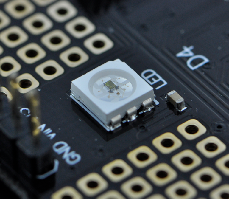
A RGB light WS2812B-4 has been put inside MiniQ 2WD plus with inner driver IC-WS2811. It can be controlled use one-wire communication method .
The sample shows color changing and flicker.

Sample Code
#include <Adafruit_NeoPixel.h>
#define PIN 4
Adafruit_NeoPixel strip = Adafruit_NeoPixel(150, PIN, NEO_GRB + NEO_KHZ800);
void setup() {
strip.begin();
strip.show(); // Initialize all pixels to 'off'
}
void loop() {
// Some example procedures showing how to display to the pixels:
colorWipe(strip.Color(255, 0, 0), 50); // Red
colorWipe(strip.Color(0, 255, 0), 50); // Green
colorWipe(strip.Color(0, 0, 255), 50); // Blue
// Send a theater pixel chase in...
theaterChase(strip.Color(127, 127, 127), 50); // White
theaterChase(strip.Color(127, 0, 0), 50); // Red
theaterChase(strip.Color( 0, 0, 127), 50); // Blue
rainbow(20);
// rainbowCycle(20);
// theaterChaseRainbow(50);
}
// Fill the dots one after the other with a color
void colorWipe(uint32_t c, uint8_t wait) {
for(uint16_t i=0; i<strip.numPixels(); i++) {
strip.setPixelColor(i, c);
strip.show();
delay(wait);
}
}
void rainbow(uint8_t wait) {
uint16_t i, j;
for(j=0; j<256; j++)
{
for(i=0; i<strip.numPixels(); i++)
{
strip.setPixelColor(i, Wheel((i+j) & 255));
}
strip.show();
delay(wait);
}
}
// Slightly different, this makes the rainbow equally distributed throughout
void rainbowCycle(uint8_t wait) {
uint16_t i, j;
for(j=0; j<256*5; j++) { // 5 cycles of all colors on wheel
for(i=0; i< strip.numPixels(); i++) {
strip.setPixelColor(i, Wheel(((i * 256 / strip.numPixels()) + j) & 255));
}
strip.show();
delay(wait);
}
}
//Theatre-style crawling lights.
void theaterChase(uint32_t c, uint8_t wait) {
for (int j=0; j<10; j++) { //do 10 cycles of chasing
for (int q=0; q < 3; q++) {
for (int i=0; i < strip.numPixels(); i=i+3) {
strip.setPixelColor(i+q, c); //turn every third pixel on
}
strip.show();
delay(wait);
for (int i=0; i < strip.numPixels(); i=i+3) {
strip.setPixelColor(i+q, 0); //turn every third pixel off
}
}
}
}
//Theatre-style crawling lights with rainbow effect
void theaterChaseRainbow(uint8_t wait) {
for (int j=0; j < 256; j++) { // cycle all 256 colors in the wheel
for (int q=0; q < 3; q++) {
for (int i=0; i < strip.numPixels(); i=i+3) {
strip.setPixelColor(i+q, Wheel( (i+j) % 255)); //turn every third pixel on
}
strip.show();
delay(wait);
for (int i=0; i < strip.numPixels(); i=i+3) {
strip.setPixelColor(i+q, 0); //turn every third pixel off
}
}
}
}
// Input a value 0 to 255 to get a color value.
// The colours are a transition r - g - b - back to r.
uint32_t Wheel(byte WheelPos)
{
if(WheelPos < 85)
{
return strip.Color(WheelPos * 3, 255 - WheelPos * 3, 0);
}
else if(WheelPos < 170)
{
WheelPos -= 85;
return strip.Color(255 - WheelPos * 3, 0, WheelPos * 3);
}
else
{
WheelPos -= 170;
return strip.Color(0, WheelPos * 3, 255 - WheelPos * 3);
}
}
### Application
**miniQ 2WD PLUS & miniQ 2WD**
MiniQ 2WD and the PLUS were meant for each other.MiniQ 2WD PLUS and MiniQ 2WD use IIC to communication, and they are connected by the Gadgteer interface . MiniQ 2WD PLUS is the host, and MiniQ 2WD works as the slave, MiniQ 2WD PLUS receives command data by wireless, then analyzes and sents it through the IIC to make command MiniQ 2WD do corresponding action.
**Notes:**There are 4 models in the "movement function": "patrol line model", " light hunter model", "Obstacle avoidance model”, and "remote control model". The parameters of the sensor in **line hunter mode** can be adjusted, that is to say, the car can adapt to each different scenes. The specific operation is as follows, when entering the patrol line mode, the car did not work directly. It needs regulation first (adjusting using three buttons, KEY1、 KEY2、 KEY3, on the front of 2WD). Press KEY1, then you can adjust the first (from left to right) sensor .Then continue to pressing KEY2 until the RGB light becomes red. (If then press KEY3, RGB light will turn green again) Press KEY1 to determine and continue to regulate the next one. Note: After the middle sensor into red, press KEY3 to change it back to green, because you need this sensor to follow the black line.) Repeat five times to regulate all the sensors. Of course, when you in the regulation of time, you need put it on the line. After five sensors adjustment, continue to press the KEY1 . 2WD will exit regulation mode, and enter working mode. Press the KEY1 if you want to adjust again. **Remote control mode** uses the remote controller attached in MiniQ 2WD kits, using "SWITCH", "VOL+","VOL-", "SLOW", "SKIP" key to represent the "stop", "go forward", "go back", "turn left", "turn right".
 There is a sample code as follow , the entire application also need **["LCD12864 Shield for Arduino"](https://www.dfrobot.com/product-1084.html)** as a display and a controller with the integrated rocker .This sample demonstrates a MiniQ common 2WD functions: buzzer, light, line patrol, light hunting, avoidance, remote control function.
**Note: the program is divided into two parts which need upload in the miniQ 2WD Plus and the car respectively.**
### sample code for PLUS
Please download [LCD library](https://github.com/CainZ/DFR0302/blob/master/JLX12864G.zip?raw=true) first.
#include<Wire.h>
#include<JLX12864G.h>
JLX12864G lcd(8,9,10,11,13);
long TimeNum=0;
char SendCommandData[]={'S','M','L','A','E','O','R','#'};//
char xReadData=0;
int Key_Num=0;
int Key_Up=0,Key_Down=0,Key_Left=0,Key_Right=0,Key_Ok=0;
byte CheckData1[]={1,3,5};
byte CheckData2[]={1,3,5,7};
char dfrobotlogo[]={
0x08,0xF8,0xF8,0x08,0x18,0xF0,0xE0,0x00,0x08,0x0F,0x0F,0x08,0x0C,0x07,0x03,0x00,
0x08,0xF8,0xF8,0x88,0xC8,0xC8,0x18,0x10,0x08,0x0F,0x0F,0x08,0x01,0x01,0x00,0x00,
0x08,0xF8,0xF8,0xC8,0xC8,0x78,0x30,0x00,0x08,0x0F,0x0F,0x08,0x03,0x0F,0x0C,0x08,
0xE0,0xF0,0x18,0x08,0x18,0xF0,0xE0,0x00,0x03,0x07,0x0C,0x08,0x0C,0x07,0x03,0x00,
0x08,0xF8,0xF8,0x48,0x48,0xF8,0xB0,0x00,0x08,0x0F,0x0F,0x08,0x08,0x0F,0x07,0x00,
0xE0,0xF0,0x18,0x08,0x18,0xF0,0xE0,0x00,0x03,0x07,0x0C,0x08,0x0C,0x07,0x03,0x00,
0x18,0x18,0x08,0xF8,0xF8,0x08,0x18,0x18,0x00,0x00,0x08,0x0F,0x0F,0x08,0x00,0x00,
};
char check[]={0xFF,0xFE,0xFC,0xF8,0xF0,0xE0,0xC0,0x80,0xFF,0x7F,0x3F,0x1F,0x0F,0x07,0x03,0x01,}; //It is a function switch indicator
char Spacebar[]={0x00,0x00,0x00,0x00,0x00,0x00,0x00,0x00,0x00,0x00,0x00,0x00,0x00,0x00,0x00,0x00,};
char FullPower[]={0xFF,0x01,0xFD,0xFD,0xFD,0xFD,0x01,0xFF,0xFF,0x80,0xBF,0xBF,0xBF,0xBF,0x80,0xFF,};//It is a full power indicator
char HalfPower[]={0xFF,0x01,0x81,0x81,0x81,0x81,0x01,0xFF,0xFF,0x80,0xBF,0xBF,0xBF,0xBF,0x80,0xFF,};//
char LowPower[]={0xFF,0x01,0x01,0x01,0x01,0x01,0x01,0xFF,0xFF,0x80,0xB8,0xB8,0xB8,0xB8,0x80,0xFF,};
char ShortagePower[]={0xFF,0x01,0x01,0x01,0x01,0x01,0x01,0xFF,0xFF,0x80,0x80,0x80,0x80,0x80,0x80,0xFF,};
void setup()
{
pinMode(7,OUTPUT);
lcd.init();
lcd.clear();
Wire.begin();
Serial1.begin(57600);
}
void loop()
{
int n=0;
lcd.graphic_8x16(3,2,dfrobotlogo,7);
lcd.string_5x7(5,5,"miniQ 2WD V3");
lcd.string_5x7(6,15,"www.dfrobot.com");
lcd.string_5x7(8,1,"Please press any key!");
digitalWrite(7,HIGH);
while(Key_Num==0)
{
Key_Scan();
}
lcd.clear();
FunctionMenu();
while(1)//Enter the cycle does not return
{
Key_Scan();
Key_Deal();
if(Key_Down==4)
{
Key_Down=1;
}
ReadPowerData();
}
}
void FunctionMenu(void)
{
lcd.string_5x7(2,9,"MusicFunction");
lcd.string_5x7(4,9,"LightsFunction");
lcd.string_5x7(6,9,"MovementFunction");
}
void MusicFunctionMode(void)
{
lcd.string_5x7(2,28,"MusicFunction");
}
void LightFunctionMode(void)
{
lcd.string_5x7(2,24,"LightsFunction");
}
void MovementFunctionMode(void)
{
lcd.string_5x7(2,9,"PatrolLine");
lcd.string_5x7(4,9,"SearchLight");
lcd.string_5x7(6,9,"ObstacleAvoidance");
lcd.string_5x7(8,9,"RemoteControl");
}
void Key_Scan(void)
{
int analog = analogRead(A0);
if(analog>=950)
{
Key_Num=0;
return;
}
else
{
Key_Num=1;
if(analog>=750&&analog<950)//Press up and key_num=1
{
delay(2);
if(analog>=750&&analog<950)
{
while(analog<950)
analog = analogRead(A0);
Key_Up++;
}
}
else if(analog>=550&&analog<750)//Press right and key_num=2
{
delay(2);
if(analog>=550&&analog<750)
{
while(analog<950)
analog = analogRead(A0);
Key_Right=1;
}
}
else if(analog>=350&&analog<550)//Press down and key_num=3
{
delay(2);
if(analog>=350&&analog<550)
{
while(analog<950)
analog = analogRead(A0);
Key_Down++;
}
}
else if(analog>=150&&analog<350)//Press ok and key_num=4
{
delay(2);
if(analog>=150&&analog<350)
{
while(analog<950)
analog = analogRead(A0);
Key_Ok=1;
}
}
else if(analog<150)//Press left and key_num=5
{
delay(2);
if(analog<150)
{
while(analog<950)
analog = analogRead(A0);
Key_Left=1;
}
}
}
}
void Key_Deal(void)
{
if(Key_Down==1)
{
Lcd_Check_Graphic(1,0);
if(Key_Ok==1)// enter music fuction menu
{
lcd.clear();
MusicFunctionMode();
IICWritData(SendCommandData[1]);
while(1)
{
Key_Scan();
Key_Ok=0;
if(Key_Left==1)
{
Key_Left=0;
Key_Down=1;
IICWritData(SendCommandData[0]);
goto Back_One_Level;//back to main menu
}
ReadPowerData();
}
}
}
if(Key_Down==2)
{
Lcd_Check_Graphic(3,0);
if(Key_Ok==1)//enter light function menu
{
lcd.clear();
LightFunctionMode();
IICWritData(SendCommandData[2]);
while(1)
{
Key_Scan();
Key_Ok=0;
if(Key_Left==1)
{
Key_Left=0;
Key_Down=2;
IICWritData(SendCommandData[0]);
goto Back_One_Level;//back to main menu
}
ReadPowerData();
}
}
}
if(Key_Down==3)
{
Lcd_Check_Graphic(5,0);
if(Key_Ok==1)//enter movement function menu
{
Key_Ok=0;
Key_Down=1;
lcd.clear();
MovementFunctionMode();
while(1)
{
Key_Scan();
if(Key_Left==1)
{
Key_Left=0;
Key_Down=3;
goto Back_One_Level;
}
if(Key_Down==1)
{
Lcd_Check_Graphic(1,1);
if(Key_Ok==1)
{
Key_Ok=0;
Key_Up=0;
lcd.clear();
lcd.string_5x7(2,20,"PatrolLineModel");//enter patrol line model
// lcd.graphic_16x16(3,1,StartData,2);
IICWritData(SendCommandData[3]);
//send line data
while(1)
{
Key_Scan();
if(Key_Left==1)
{
Key_Ok=0;
Key_Left=0;
Key_Down=1;
IICWritData(SendCommandData[0]);
goto Back_Two_Level_Move;//back to second-level menu
}
ReadPowerData();
}
Back_Two_Level_Move://second-level menu
lcd.clear();
MovementFunctionMode();
}
}
if(Key_Down==2)
{
Lcd_Check_Graphic(3,1);
if(Key_Ok==1)
{
Key_Ok=0;
lcd.clear();
lcd.string_5x7(2,17,"SearchLightModel");
IICWritData(SendCommandData[4]);
//send light data
while(1)
{
Key_Scan();
if(Key_Left==1)
{
Key_Ok=0;
Key_Left=0;
Key_Down=2;
IICWritData(SendCommandData[0]);
goto Back_Two_Level_Move;//back to second-level menu
}
ReadPowerData();
}
}
}
if(Key_Down==3)
{
Lcd_Check_Graphic(5,1);
if(Key_Ok==1)
{
Key_Ok=0;
lcd.clear();
lcd.string_5x7(2,2,"ObstacleAvoidanceModel");
IICWritData(SendCommandData[5]);
//send OBSTACLEAVOIDANCE data
while(1)
{
Key_Scan();
if(Key_Left==1)
{
Key_Ok=0;
Key_Left=0;
Key_Down=3;
IICWritData(SendCommandData[0]);
goto Back_Two_Level_Move;//back to second-level menu
}
ReadPowerData();
}
}
}
if(Key_Down==4)
{
Lcd_Check_Graphic(7,1);
if(Key_Ok==1)
{
Key_Ok=0;
lcd.clear();
lcd.string_5x7(2,12,"RemoteControlModel");
IICWritData(SendCommandData[6]);
//send Remote data
while(1)
{
Key_Scan();
if(Key_Left==1)
{
Key_Ok=0;
Key_Left=0;
Key_Down=4;
IICWritData(SendCommandData[0]);
goto Back_Two_Level_Move;//back to second-level menu
}
SerialReadWriteData();
ReadPowerData();
}
}
}
if(Key_Down==5)
Key_Down=1;
ReadPowerData();
}
Back_One_Level://back to main menu
lcd.clear();
FunctionMenu();
}
}
}
void SerialReadWriteData(void)
{
if(Serial1.available())
{
char SerialData = Serial1.read();
switch(SerialData)
{
case 'w':
IICWritData('w');
break;
case 'a':
IICWritData('a');
break;
case 's':
IICWritData('s');
break;
case 'd':
IICWritData('d');
break;
default:
IICWritData('S');
break;
}
}
}
void Lcd_Check_Graphic(byte CheckNum,char RowsNum)//The check of indicator switch function
{
if(RowsNum==0)
{
for(int i=0;i<3;i++)
{
if(CheckData1[i]==CheckNum)
lcd.graphic_8x16(CheckNum,1,check,1);
else
lcd.graphic_8x16(CheckData1[i],1,Spacebar,1);
}
}
else if(RowsNum==1)
{
for(int j=0;j<4;j++)
{
if(CheckData2[j]==CheckNum)
lcd.graphic_8x16(CheckNum,1,check,1);
else
lcd.graphic_8x16(CheckData2[j],1,Spacebar,1);
}
}
}
void IICWritData(char data)
{
Wire.beginTransmission(4); //send data to the slave named 4
Wire.write(data); // send a byte in variable data
Wire.endTransmission(); // stop sending
}
void IICReadData(void)
{
Wire.requestFrom(4, 1); //request the slave to upload a byte
while(Wire.available()>0) // when data sent from the slave to the host
{
xReadData = Wire.read(); //assign a value to 'xReadData'
}
}
// electric quantity reading function
void ReadPowerData(void)
{
TimeNum++;
if(TimeNum==10)
{
TimeNum=0;
IICReadData();
switch(xReadData)
{
case'3':
{
lcd.graphic_8x16(1,121,FullPower,1);
digitalWrite(7,HIGH);
break;
}
case'2':
{
lcd.graphic_8x16(1,121,HalfPower,1);
digitalWrite(7,HIGH);
break;
}
case'1':
{
lcd.graphic_8x16(1,121,LowPower,1);
digitalWrite(7,HIGH);
break;
}
case'0':
{
lcd.graphic_8x16(1,121,ShortagePower,1);
digitalWrite(7,LOW);
break;
}
}
}
}
sample code for 2WD
    #include <Wire.h>
    #include <Adafruit_NeoPixel.h>
    #include <IRremote.h>
    #if defined(ARDUINO) && ARDUINO >= 100
    #define printByte(args)  write(args);
    #else
    #define printByte(args)  print(args,BYTE);
    #endif
    uint8_t empty[8] = {0x0,0x0,0x0,0x0,0x0,0x0,0x0,0x1f};
    uint8_t heart[8] = {0x0,0xa,0x1f,0x1f,0xe,0x4,0x0,0x0};
    #define address 0x1e

    int length;
    #define RGB_ws2812 10
    Adafruit_NeoPixel strip = Adafruit_NeoPixel(60, RGB_ws2812, NEO_GRB + NEO_KHZ800);

    #define EN1 6//pin for run the right motor
    #define IN1 7//pin for control right motor direction
    #define EN2 5//pin for run the left motor
    #define IN2 12//pin for control left motor direction

    #define FORW 0//go frword
    #define BACK 1//go back

    #define IR_IN  17//IR receiver pin
    #define L_IR 13//left ir transmitter pin
    #define R_IR 8//right ir transmitter pin

    #define BUZZER 16//buzzer pin

    #define Vr   5// Voltage reference

    #define NTD0 -1
    #define NTD1 294
    #define NTD2 330
    #define NTD3 350
    #define NTD4 393
    #define NTD5 441
    #define NTD6 495
    #define NTD7 556

    #define NTDL1 147
    #define NTDL2 165
    #define NTDL3 175
    #define NTDL4 196
    #define NTDL5 221
    #define NTDL6 248
    #define NTDL7 278

    #define NTDH1 589
    #define NTDH2 661
    #define NTDH3 700
    #define NTDH4 786
    #define NTDH5 882
    #define NTDH6 990
    #define NTDH7 112
    //define all the keys' frequency of D major
    #define WHOLE 1
    #define HALF 0.5
    #define QUARTER 0.25
    #define EIGHTH 0.25
    #define SIXTEENTH 0.625
    //define all the beats
    int tune1[]=                 //list keys according to music
    {
      NTDH3,NTDH3,NTDH2,NTDH3,NTD6,NTDH3,NTD6,NTD5,
      NTDH2,NTDH1,NTDH2,NTDH3,NTDH2,NTDH1,
      NTD6,NTDH3,NTDH2,NTDH3,NTDH2,NTDH1,NTD7,
      NTD6,NTD5,NTD6,NTD7,NTD6,NTD5
    };
    float durt1[]=                   //Corresponding beats according to key list
    {
      0.5,0.5,1,0.5,1,1.5,1,1,
      0.5,0.5,1,0.5,1,2,
      1,1,0.5,0.5,1,0.5,1,
      0.5,0.5,1,0.5,1,2
    };

    int tonepin=16;
    char xReadWriteData='S';
    int   count;////count the motor speed pulse
    float data[7]={0X00,0X00,0X00,0X00,0x00,0xff,0x00};//store 8-channel A/D converter value
    char  value[5]={0x00,0x00,0x00,0x00,0x00};//store the value read from the sensors
    char  key_1=0x00,key_2=0x00,key_3=0x00;//count of 3 keys
    //count mileage
    int    count_r=0,count_l=0;//count pluse return by teo wheel
    //remote parameter
    IRrecv irrecv(IR_IN);
    decode_results results;
    int SpeedNumL=100;
    int SpeedNumR=100;

    void Motor_Control(int M1_DIR,int M1_EN,int M2_DIR,int M2_EN)//control motor
    {
      //////////M1////////////////////////
      if(M1_DIR==FORW)//M1 motor direction
          digitalWrite(IN1,FORW); //forward
      else
        digitalWrite(IN1,BACK);//back
      if(M1_EN==0)
          analogWrite(EN1,LOW);//stop
      else
        analogWrite(EN1,M1_EN);//set speed

      ///////////M2//////////////////////
      if(M2_DIR==FORW) //M2 motor direction
          digitalWrite(IN2,FORW); //forward
      else
        digitalWrite(IN2,BACK);///back
      if(M2_EN==0)
          analogWrite(EN2,LOW);//stop
      else
      analogWrite(EN2,M2_EN);//set speed
    }
    //avoidance
    void L_Send40KHZ(void)//left ir transmitter sends 40kHZ pulse

    {
      int i;
      for(i=0;i<24;i++)
      {
        digitalWrite(L_IR,LOW);
        delayMicroseconds(8);
        digitalWrite(L_IR,HIGH);
        delayMicroseconds(8);
      }
    }
    void R_Send40KHZ(void)//right ir transmitter sends 40kHZ pulse
    {
      int i;
      for(i=0;i<24;i++)
      {
        digitalWrite(R_IR,LOW);
        delayMicroseconds(8);
        digitalWrite(R_IR,HIGH);
        delayMicroseconds(8);
      }
    }
    //mileage counting
    void LEFT(void)
    {
     //pluse count return by two wheels
     //if(++count_l=100)
        count_l++;
    }
    void RIGHT(void)
    {
     //pluse count return by right side wheel
    // if(++count_r=100)
        count_r++;
    }
    void pcint0_init(void)//initial the interrupt
    {
      PCICR = 0X01;//enable interrupt when pins in group 0 changes
      PCMSK0 = 0X01;//enable interrupt when pin 0 in group 0 changes
    }
    ISR(PCINT0_vect)//motor encoder interrupt
    {
      count++;
    }
    void Obstacle_Avoidance(void)
    {
      char i;
      count=0;
      for(i=0;i<20;i++)//left transmitter sends 20 pulses
      {
        L_Send40KHZ();
        delayMicroseconds(600);
      }
      if(count>20)//if recieved a lot pulse , it means there's a obstacle
      {
          Motor_Control(BACK,SpeedNumR,BACK,SpeedNumL);
          delay(50);
          Motor_Control(BACK,SpeedNumR,FORW,SpeedNumL);
          delay(50);
      }
      else
      {
          Motor_Control(FORW,SpeedNumR,FORW,SpeedNumL);
      }

      count=0;
      for(i=0;i<20;i++)//right transmitter sends 20 pulses
      {
        R_Send40KHZ();
        delayMicroseconds(600);
      }
      if(count>20)
      {
          Motor_Control(BACK,SpeedNumR,BACK,SpeedNumL);
          delay(50);
          Motor_Control(FORW,SpeedNumR,BACK,SpeedNumL);
          delay(50);
      }
      else
      {
          Motor_Control(FORW,SpeedNumR,FORW,SpeedNumL);
      }

    }
    //read volt value in analog port
    void Read_Value(void)
    {
      int i;
      for(i=0;i<7;i++)
      {
        data[i]=analogRead(i);//store the value read from the analog port
        data[i]= ((data[i]*Vr)/1024); //turn to analog value
      }
    }
    //line follower
    void value_adjust(unsigned char num)//set sensor parameter
    {
      if(num==1)//set the first sensor
      {
        if(data[0]>value[0])
        {
          colorWipe(strip.Color(0, 255, 0), 5); // Red
        }
        else
        {
          colorWipe(strip.Color(255, 0, 0), 1); // Green
        }
      }
      if(num==2)//set the second sensor
      {
        if(data[1]>value[1])
        {
          colorWipe(strip.Color(0, 255, 0), 1); // Red
        }
        else
        {
          colorWipe(strip.Color(255, 0, 0), 1); // Green
        }
      }
      if(num==3)//set the third sensor
      {
        if(data[2]>value[2])
        {
          colorWipe(strip.Color(0, 255, 0), 1); // Red
        }
        else
        {
          colorWipe(strip.Color(255, 0, 0), 1); // Green
        }
      }
      if(num==4)//set the forth sensor
      {
        if(data[3]>value[3])
        {
          colorWipe(strip.Color(0, 255, 0), 1); // Red
        }
        else
        {
          colorWipe(strip.Color(255, 0, 0), 1); // Green
        }
      }
      if(num==5)//set the fifth sensor
      {
        if(data[4]>value[4])
        {
          colorWipe(strip.Color(0, 255, 0), 1); // Red
        }
        else
        {
          colorWipe(strip.Color(255, 0, 0), 1); // Green
        }
      }
    }
    void huntline_deal(void)
    {
     if(data[0]>(value[0]-1)&&data[1]>(value[1]-1)&&data[2]<(value[2])&&data[3]>(value[3]-1)&&data[4]>(value[4]-1))
        Motor_Control(FORW,100,FORW,100);//go forword
      else if(data[0]>(value[0]-1)&&data[1]>(value[1]-1)&&data[2]<(value[2]-1)&&data[3]<(value[3]-1)&&data[4]>(value[4]-1))
        Motor_Control(BACK,20,FORW,100);//turn right
      else if(data[0]>(value[0]-1)&&data[1]>(value[1]-1)&&data[2]>(value[2]-1)&&data[3]<(value[3]-1)&&data[4]>(value[4]-1))
        Motor_Control(BACK,100,FORW,100);//fast turn right
      else if(data[0]>(value[0]-1)&&data[1]>(value[1]-1)&&data[2]>(value[2]-1)&&data[3]<(value[3]-1)&&data[4]<(value[4]-1))
        Motor_Control(BACK,100,FORW,100);//fast turn right
      else if(data[0]>(value[0]-1)&&data[1]>(value[1]-1)&&data[2]>(value[2]-1)&&data[3]>(value[3]-1)&&data[4]<(value[4]-1))
        Motor_Control(BACK,100,FORW,100);//fast turn right
      else if(data[0]>(value[0]-1)&&data[1]<(value[1]-1)&&data[2]<(value[2]-1)&&data[3]>(value[3]-1)&&data[4]>(value[4]-1))
        Motor_Control(FORW,100,BACK,20);//turn left
      else if(data[0]>(value[0]-1)&&data[1]<(value[1]-1)&&data[2]>(value[2]-1)&&data[3]>(value[3]-1)&&data[4]>(value[4]-1))
        Motor_Control(FORW,100,BACK,100);//fast turn left
      else if(data[0]<(value[0]-1)&&data[1]<(value[1]-1)&&data[2]>(value[2]-1)&&data[3]>(value[3]-1)&&data[4]>(value[4]-1))
        Motor_Control(FORW,100,BACK,100);//fast turn left
      else if(data[0]<(value[0]-1)&&data[1]>(value[1]-1)&&data[2]>(value[2]-1)&&data[3]>(value[3]-1)&&data[4]>(value[4]-1))
        Motor_Control(FORW,100,BACK,100);//fast turn left
    }
    //light hunter
    void hunt_light(void)
    {
      if (data[5]>3.5)   //measure from present environment
        Motor_Control(BACK,SpeedNumR,FORW,SpeedNumL);//turn right
      else if (data[5]< 1.5)
        Motor_Control(FORW,SpeedNumR,BACK,SpeedNumL);//
      else
        Motor_Control(FORW,0,FORW,0);//stop
    }
    //remote
    void dump(decode_results *results)
    {
      if(results->value==0x00fd00ff)
      {
        Motor_Control(FORW,0,FORW,0);
      }
      if(results->value==0x00fd807f)
      {
        Motor_Control(FORW,100,FORW,100);
      }
      if(results->value==0x00fd906f)
      {
        Motor_Control(BACK,100,BACK,100);
      }
      if(results->value==0x00fd20df)
      {
        Motor_Control(FORW,100,BACK,100);//turn left
      }
      if(results->value==0x00fd609f)
      {
        Motor_Control(BACK,100,FORW,100);//turn right
      }
    }
    //buzzer function
    void buzzer(void)
    {
      digitalWrite(BUZZER,HIGH);//buzzer sound
      delay(1);
      digitalWrite(BUZZER,LOW);//
      delay(10);
    }
    //key scan
    void key_scan(void)
    {
      if(data[6]>4.50&&data[6]<6.00)//without button
        return;
      else
      {
        if(data[6]>=0.00&&data[6]<0.80)//push key 1
        {
          delay(10);//Debounce delay
          if(data[6]>=0.00&&data[6]<0.80)//do push key 1
          {
            buzzer();
            while(data[6]>=0.00&&data[6]<0.80)
             Read_Value();
            key_1++;//count key 1
            if(key_1>=1&&key_1<=5)
              value_adjust(key_1);//adjust sensor parameter
          }
        }
        else if(data[6]>=0.80&&data[6]<3)//push key 2
        {
          delay(10);
          if(data[6]>=0.80&&data[6]<3)
          {
            buzzer();
            while(data[6]>=0.50&&data[6]<3)
             Read_Value();
            if(key_1>=1&&key_1<=5)//count of key 1 range in 1 to 5
            {
              value[key_1-1]++;//the limit where sensor can distinguish do the "++" count
              value_adjust(key_1);//adjust sensor parameter
            }
            else
            {
              key_2++;//count key 2
            }
          }
        }
        else if(data[6]>=3&&data[6]<4)
        {
          delay(10);
          if(data[6]>=3&&data[6]<4)
          {
            buzzer();
            while(data[6]>=3&&data[6]<4)
              Read_Value();
            if(key_1>=1&&key_1<=5)
            {
              value[key_1-1]--;//the limit where sensor can distinguish do the "--" count
              value_adjust(key_1);
            }
            else
            {
              key_3++;
            }
          }
        }
      }
    }
    void key_deal()// hunt line
    {
      if(key_1==6)
      {
        huntline_deal();
        key_2=0x00;
        key_3=0x00;
      }
      else if(key_1 == 7)
      {
         key_1 = 0;
         Motor_Control(FORW,0,FORW,0);//stop
      }
    }
    //low voltage check
    void low_voltage_check(void)
    {
        float voltage_num=analogRead(A9);
        voltage_num=(15*voltage_num)/2048;
       if(voltage_num<4.0||voltage_num>7.0)
       {
         while(1)
         {
           voltage_num=analogRead(A9);
            voltage_num=(15*voltage_num)/2048;
            if(voltage_num>=4.0&&voltage_num<=7.0)
              break;
            buzzer();
            colorWipe(strip.Color(0, 255, 0), 1); // Red
            colorWipe(strip.Color(0, 0, 0), 1);
         }
       }
    }
    void Velocity_function(void)//speed management
    {
      if(count_l>count_r)
      {
        SpeedNumL=SpeedNumL-1;
        SpeedNumR=SpeedNumR+1;
      }
      else if(count_l<count_r)
      {
        SpeedNumL=SpeedNumL+1;
        SpeedNumR=SpeedNumR-1;
      }
      count_l=0;
      count_r=0;
    }
    void colorWipe(uint32_t c, uint8_t wait)
    {
      for(uint16_t i=0; i<strip.numPixels(); i++)
     {
          strip.setPixelColor(i, c);
          strip.show();
          delay(wait);
      }
    }

    void setup()
    {
      pinMode(5,OUTPUT);//init the motor driver pins
      pinMode(6,OUTPUT);
      pinMode(7,OUTPUT);
      pinMode(12,OUTPUT);

      pinMode(8,OUTPUT);
      pinMode(10,OUTPUT);
      pinMode(13,OUTPUT);
      pinMode(14,OUTPUT);
      pinMode(16,OUTPUT);
      pinMode(17,INPUT);
      irrecv.enableIRIn();
      strip.begin();
      strip.show();

      length=sizeof(tune1)/sizeof(tune1[0]);   //calculate length

      Wire.begin(4);//name the slave with  4
      Wire.onReceive(receiveEvent);//login the event slave received
      Wire.onRequest(requestEvent);// login the event host requested

      attachInterrupt(2,RIGHT,FALLING);
      attachInterrupt(3,LEFT,FALLING);
      Motor_Control(FORW,0,FORW,0);//stop motor
    }
    void loop()
    {
      switch(xReadWriteData)
      {
        case'S':
          Motor_Control(FORW,0,FORW,0);
          break;
        case'M':
          MusicFunction();
          break;
        case'L':
          RGBFunction();
          break;
        case'A':
          LineFunction();
          break;
        case'E':
          LightFuntion();
          break;
        case'O':
          ObstacleFunction();
          break;
        case'R':
          RemoteFunction();
          break;
        case'w':
          Motor_Control(FORW,SpeedNumR,FORW,SpeedNumL);//go forword
          break;
        case'a':
          Motor_Control(FORW,SpeedNumR,BACK,SpeedNumL);//turn left
          break;
        case's':
          Motor_Control(BACK,SpeedNumR,BACK,SpeedNumL);//go back
          break;
        case'd':
          Motor_Control(BACK,SpeedNumR,FORW,SpeedNumL);//turn right
          break;
      }
      Velocity_function();
    //  low_voltage_check();
      colorWipe(strip.Color(0, 0, 0), 1);
    }

    // do when slave receive data
    void receiveEvent(int howMany)
    {
      while( Wire.available()>1) // do loop until the data packet have the last byte
      {
        char c = Wire.read(); // receive data as a byte
      }
       //receive the last data
      xReadWriteData = Wire.read();    // receive data as integer
    }

    //do when the event host requested
    void requestEvent()
    {
      float analog = analogRead(A9);
      analog =(15*analog)/2048;
      if(analog>4.7)
        Wire.write( '3');
      else if(analog>4.3)
        Wire.write( '2');
      else if(analog>3.9)
        Wire.write( '1');
      else
        Wire.write( '0');
     // response and send a byte of data to the host
    }

    uint32_t Wheel(byte WheelPos)
    {
      if(WheelPos < 85)
      {
       return strip.Color(WheelPos * 3, 255 - WheelPos * 3, 0);
      }
      else if(WheelPos < 170)
      {
       WheelPos -= 85;
       return strip.Color(255 - WheelPos * 3, 0, WheelPos * 3);
      }
      else
      {
       WheelPos -= 170;
       return strip.Color(0, WheelPos * 3, 255 - WheelPos * 3);
      }
    }

    void rainbow(uint8_t wait)
    {
      uint16_t i, j;

      for(j=0; j<256; j++)
      {
        for(i=0; i<strip.numPixels(); i++)
        {
          strip.setPixelColor(i, Wheel((i+j) & 255));
        }
        strip.show();
        delay(wait);
      }
    }

    // Slightly different, this makes the rainbow equally distributed throughout
    void rainbowCycle(uint8_t wait)
    {
      uint16_t i, j;

      for(j=0; j<256*5; j++)
      { // 5 cycles of all colors on wheel
        for(i=0; i< strip.numPixels(); i++)
        {
          strip.setPixelColor(i, Wheel(((i * 256 / strip.numPixels()) + j) & 255));
        }
        strip.show();
        delay(wait);
      }
    }

    void MusicFunction(void)//
    {
      for(int x=0;x<length;x++)
      {
        tone(tonepin,tune1[x]);
        delay(350*durt1[x]);   //beat delay accroding to the music
        noTone(tonepin);
      }
    }

    void RGBFunction(void)//
    {
      rainbow(5);
      rainbowCycle(5);
    }

    void LineFunction(void)//
    {
      //buzzer();
      Read_Value();
      key_scan();
      key_deal();
    }

    void LightFuntion(void)//
    {
       Read_Value();
       hunt_light();
       Velocity_function();
    }

    void ObstacleFunction(void)//
    {
      pcint0_init();//initial the interrupt
      sei();     //enable global interrupt
      Obstacle_Avoidance();
      Velocity_function();
    }
    void RemoteFunction(void)
    {  Motor_Control(FORW,0,FORW,0);//run motor
      while(1)
      {
       if(irrecv.decode(&results))
       {
          dump(&results);
          irrecv.resume();
       }
      }
    }
FAQ
| Q&A | Some general Arduino Problems/FAQ/Tips |
|---|---|
| A | For any questions, advice or cool ideas to share, please visit the DFRobot Forum. |
