Introduction
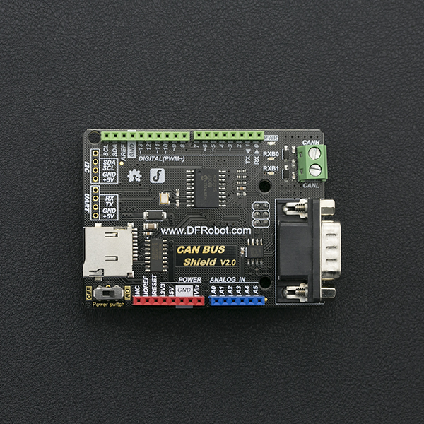
The CAN-BUS arduino shield v2.0 is designed for the Arduino Microcontroller. It is compatible with the Arduino standard interface and can be stacked on an Arduino UNO, arduino Leonardo or arduino MEGA board. The shield integrates an MCP2515 CAN-BUS chip on the shield and has a CAN-BUS transceiver function. With an on-board DB9 and CAN-BUS connector you can choose a suitable port according to your host device. There is also an integrated MicroSD socket for data storage - a perfect solution for data logging applications.
Features
- Capable of transmitting and receiving both standard and remote frames
- Supports rotational and interrupt detection reception methods
- Supports UART, i2C and DB9 terminal interfaces
- Supports SD card data storage
- Supports Arduino mainboard power supply or DB9 power supply (Switch)
Specification
- Chip: MCP2515
- Power supply: 3.3 ~ 5V Arduino board power supply or DB9 interface power supply
- Dimension: 76x54x19mm / 2.99x2.12x0.75 inches
- Weight: 40g
Board Overview
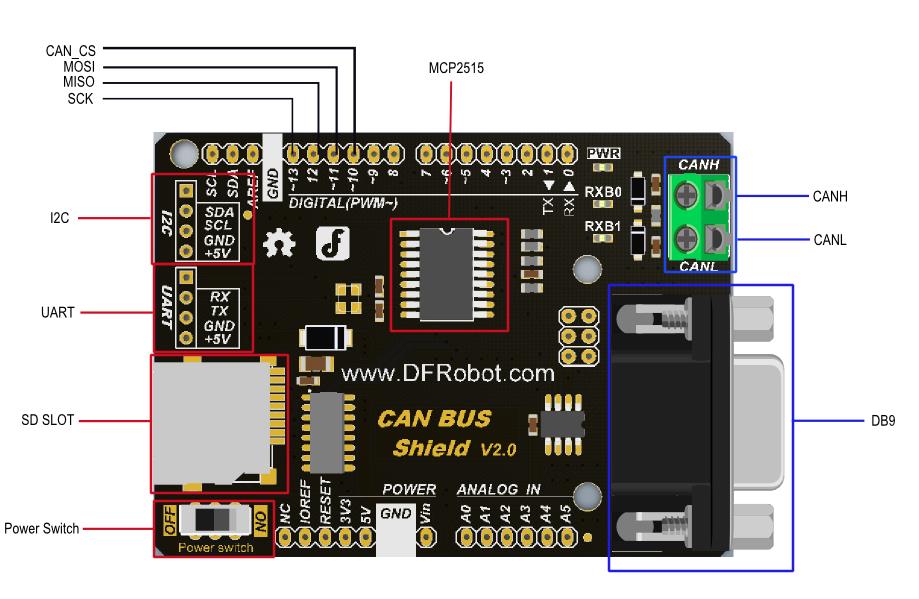
 Two power-supply modes:
Power switch: "ON", powered by DB9 port
Power switch: "OFF", powered by Arduino board
Note:
- The Arduino board can be powered from a 7V source, the switch should be "ON"
- The Arduino board can be powered from the USB and DB9 simultaneously but if the Arduino board is powered by DC-Vin port, the power switch should be turned off to avoid damage to the shield and the board.
How to Configure the CAN-BUS Node
This section will detail how to configure the CAN-BUS Node
1. CAN-BUS Node (Device)
What is CAN-BUS Node? The CAN-bus is a local area network control protocol. In a local area network there are multiple devices connected. Each device is called "Node". There is a CAN-bus protocol controller on each node (control chip). Refer to CAN-BUS WIKIPEDIA
2. CAN-BUS nodes can be used as a data receiver or data transmitter. So we call the CAN-bus node a "transceiver"
3. There is no concept of "Address" in CAN-BUS protocol, instead each device is distinguished by an "ID". Every device has a special ID in the node.
4. The CAN-BUS node relies on its hardware proof function to implement a selective receipt of Data frame from special ID at initialization time. We can call the following command to configure the special ID: init_Mask(Masker_t Masker_num, INT8U ext, INT32U ulData) and init_Filter(Filter_t Filter_num, INT8U ext, INT32U Data)
5. The data sent by any node in the network can be selectively received by the other nodes. This node can also selectively receive data sent by other ones.
The following is a simple scenario to demonstrate how it works:
There are 5 nodes in the network; A, B, C, D and E. If Node B can only receive data from ID 0x06, when Node A wants to send "Hello world" to Node B, you can call sendMsgBuf(0x06, 0, 12, "hello world") function to implement this process.
Meanwhile, what about the other nodes circumstance?
Assumption:
- Node B data frame receiving ID: 0x06
- Node C data frame receiving ID: 0x06 and 0x08
- Node D data frame receiving ID: 0x07
- Node E data frame receiving ID: Anyone
Then,
- When Node A send data frame to ID 0x06, the available Node: B, C, E
- When Node A send data frame to ID 0x07, the available Node: D, E
- When Node A send data frame to ID 0x08, the available Node: C, E
- When Node A send data frame to ID 0x12, the available Node: E
Arduino Library Function
MCPCAN(INT8U _CS)
Description: Constructor, specify the CAN-BUS Shield V1.0 SPI chip select pin.
Parameter:
- _CS: Chip select
Return: None
Example:
MCPCAN CAN(4); //Instantiate a Object with MCPCAN class, D4 is Arduino SPI CS pin.
void init(void)
Description: Initialize SPI module; reset MCP2515.
Parameter:
None
Return: None
Example:
This function should be called at first, initialize CAN-BUS MCU.
INT8U begin(INT8U speedset)
Description: Initialize setting CAN-BUS buadrate, follow the init() function.
Parameter:
- speedset: Baudrate: CAN_5KBPS, CAN_10KBPS, CAN_20KBPS, CAN_31K25BPS, CAN_33KBPS, CAN_40KBPS, CAN_50KBPS, CAN_80KBPS, CAN_83K3BPS, CAN_95KBPS, CAN_100KBPS, CAN_125KBPS, CAN_200KBPS, CAN_250KBPS, CAN_500KBPS, CAN_1000KBPS.
Return: If the initialization is successful, return "CAN_OK"; if initialization fails, return "CAN_FAILINIT".
Example:
begin(CAN_500KBPS);
INT8U sendMsgBuf(INT32U id, INT8U ext, INT8U len, INT8U *buf)
Introduction: Send a set of data frame
Parameter:
- id: Data frame ID
- ext: "ext = 0", it is a standard frame; "ext = 1", it is an extended frame.
- len: data length, len < 8
- buf: Data buffer point
Return: If success, returns "CAN_OK"; if timeout, returns "CAN_SENDMSGTIMEOUT"; If you fail to get the next free buffer, it returns "CAN_GETTXBFTIMEOUT".
Example:
unsigned char data[8] = {'D', 'F', 'R', 'O', 'B', 'O', 'T', '!'};
sendMsgBuf(0x06, 0, sizeof(data), data);
INT8U MCPCAN::setMsg(INT32U id, INT8U ext, INT8U len, INT8U rtr, INT8U *pData)
Introduction: Send remote sending request message.
Parameter:
- id: Data frame ID
- ext: "ext = 0", it is a standard frame; "ext = 1", it is an extended frame.
- len: data length, len < 8
- rtr: "rtr = 1", it is a Remote sending request frame; "rtr = 0", it is a data frame.
- buf: Data buffer point
Return: If success, returns "CAN_OK"; if timeout, returns "CAN_SENDMSGTIMEOUT"; If you fail to get the next free buffer, it returns "CAN_GETTXBFTIMEOUT".
Example:
unsigned char data[8] = {'D', 'F', 'R', 'O', 'B', 'O', 'T', '!'};
setMsg(0x06, 0, sizeof(data), 0, data);
INT8U isRemoteRequest(void)
Introduction: Check whether it is a remote frame
Parameter:
None
Return: "1", Yes; "0", No
INT8U init_Mask(Masker_t Masker_num, INT8U ext, INT32U Data)
Introduction: Initialize the mask register
Parameter:
- Masker_num: mask register name: MCP_RXM0、MCP_RXM1; If Masker_num = MCP_RXM0, initialize the mask register 0 (mask register 0 receives data from buffer0); if Masker_num = MCP_RXM1, initialize the mask register 1 (mask register 1 receives data from buffer1).
- ext: "ext=0", configure standard frame with mask register setting; "ext = 1", configure extended frame with mask register setting.
- Data: Write this data into mask register, to configure which register will be blocked.
Returns: if success, returns "MCP_OK"; if fail, returns "MCP_FAIL"
Example:
init_Mask(MCP_RXM0, 0, 0x3ff); //follow the init() function, before the begin() one. Implement a standard filter frame from 0~9 bit, 10 bit in all, because the binary form of "0x3ff" is "11 1111 1111".
INT8U checkReceive(void)
Introduction: check the validity of received data frame.
Parameter:
None
Return: If the shield receives the valid data frame, return "CAN_MSGAVAIL"; if no, return "CAN_NOMSG";
Example:
Check the validity of received data frame after CAN-BUS works. You can rotational call this function to detect it, refer to the following example.
INT8U init_Filter(Filter_t Filter_num, INT8U ext, INT32U Data)
Introduction: Initialize the message acceptance filter register.
Parameter:
- Filter_num: Message acceptance filter number, could be MCP_RXF0, MCP_RXF1, MCP_RXF2, MCP_RXF3, MCP_RXF4, MCP_RXF5.
- ext: if "ext=0", it means the message acceptance filter receive standard data frame message only; if "ext=1", it means the message acceptance filter receive extended data frame message only.
- Data: Filtered message ID. Only the data frame with filtered id can be received by CAN controller. So an upcoming data frame whether can be received depends the value in MCP_RXM0/MCP_RXM1 in init_Mask() function, the value in MCP_RXF0 registers in init_Filter() function and upcoming message identifier ID. These three values can be looked up on the Table below. If every true result is received, then the message will be received by the CAN controller. Otherwise, it will be discarded.
Filter/Mask Register Truth Table
| Mask Bit | Filter Bit | Message Identifiter Bit | Accept or Reject bit n |
|---|---|---|---|
| 0 | X | x | Accept |
| 1 | 0 | 0 | Accept |
| 1 | 0 | 1 | Reject |
| 1 | 1 | 0 | Reject |
| 1 | 1 | 1 | Accept |
Note: X = Random Variable
E.g.
If you configure MCP_RXM0 with 0x7ff with init_Mask(MCP_RXM0, 0, 0x7ff), it means it will mask the 11 bit of the standard frame. Meanwhile the init_Filter(MCP_RXF0, 0, 0x20) function will configure MCP_RXF0 register as 0x20 (000 0010 0000), filter with 0x7ff (111 1111 1111). if every value is true, the ID will be received. But if there is a false value, this ID will be discarded. In this case, MCP2515 can receive the message with ID 0x20 only. And you can also modify init_Mask(MCP_RXM0, 0, 0x7ff) to init_Mask(MCP_RXM0, 0, 0x7DF), it also support 0x20 ID.
Return: "CAN_OK" means reading successfully; Contrarily, return "MCP_FA".
Example:
init_Mask(MCP_RXM0, 0, 0x7ff);
init_Filter(MCP_RXF0, 0, 0x04); //After init() function, before begin() function. Working withinit_Mask()function. Set 0x04 as CAN controller receiving ID.
INT8U readMsgBuf(INT8U *len, INT8U *buf)
Introduction: Read data from MCP2515 receiving buffer.
Parameter:
- len: Save the receiving data length
- buf: Save the receiving data
Return: "CAN_OK" means reading successfully; Contrarily, return "CAN_NOMSG".
INT8U readMsgBufID(INT32U *ID, INT8U *len, INT8U *buf)
Introduction: Read data from MCP2515 receiving buffer and read this data frame ID.
Parameter:
- ID: Save the data frame ID
- len: Save the receiving data length
- buf: Save the receiving data
Return: "CAN_OK" means reading successfully; Contrarily, return "CAN_NOMSG".
INT8U checkError(void)
Introduction: MCP2515 control error inquiry
Parameter:
Nono
Return: "CAN_CTRLERROR" means it sends the control error; Contrarily, return "CAN_OK".
INT32U getCanId(void)
Introduction: Get the current data frame's ID
Parameter:
None
Return: Data frame ID
You can get the data frame ID with this command, after you receive the data frame. Refer to the following examples.
INT8U isExtendedFrame(void)
Introduction: Check whether it is a extended frame.
Parameter:
None
Return: "1", Yes; "0", No
This command is called in receiving interrupt handler function, to check whether the data frame is a standard data frame or an extended data frame.
Tutorial
Requirements
- Hardware
- arduino UNO x3
- CAN-BUS Shield V2 x3
- Dupont Cable x4
- Software
Basic CAN BUS Receiving and sending function (receiving: polling mode)
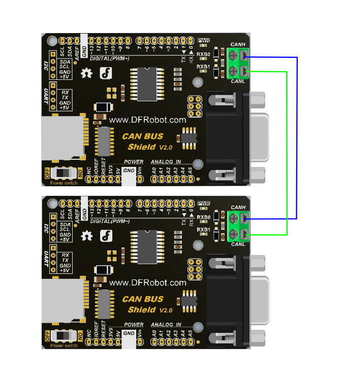
In this section we will demonstrate basic CAN BUS receiving and sending functions. Receiving uses polling mode. You can accept any ID standard data frame or extended frame. The transmitting node sends a standard data frame which ID is 0x06 per 100ms.
Connection Diagram
Sample Code
Receiver Code
/******************************************************************************
* demo: CAN-BUS Shield, receive data with check mode
* send data coming to fast, such as less than 10ms, you can use this way
* Jansion, 2015.5.27
******************************************************************************/
#include <SPI.h>
#include "df_can.h"
const int SPI_CS_PIN = 10;
MCPCAN CAN(SPI_CS_PIN);                                    // Set CS pin
void setup()
{
      Serial.begin(115200);
      int count = 50;                                     // the max numbers of initializint the CAN-BUS, if initialize failed first!.
      do {
          CAN.init();   //must initialize the Can interface here!
          if(CAN_OK == CAN.begin(CAN_500KBPS))                   // init can bus : baudrate = 500k
          {
              Serial.println("DFROBOT's CAN BUS Shield init ok!");
              break;
          }
          else
          {
              Serial.println("DFROBOT's CAN BUS Shield init fail");
              Serial.println("Please Init CAN BUS Shield again");

              delay(100);
              if (count <= 1)
                  Serial.println("Please give up trying!, trying is useless!");
          }

      }while(count--);

}
void loop()
{
      unsigned char len = 0;
      unsigned char buf[8];

      if(CAN_MSGAVAIL == CAN.checkReceive())            // check if data coming
      {
          CAN.readMsgBuf(&len, buf);    // read data,  len: data length, buf: data buf

          for(int i = 0; i<len; i++)    // print the data
          {
              Serial.print(buf[i]);
              Serial.print("\t");
          }
          Serial.println();
      }
}
Sender code
 // demo: CAN-BUS Shield, send data
  #include <df_can.h>
  #include <SPI.h>

  const int SPI_CS_PIN = 10;

  MCPCAN CAN(SPI_CS_PIN);                                    // Set CS pin

  void setup()
  {
      Serial.begin(115200);
      int count = 50;                                     // the max numbers of initializint the CAN-BUS, if initialize failed first!.
      do {
          CAN.init();   //must initialize the Can interface here!
          if(CAN_OK == CAN.begin(CAN_500KBPS))                   // init can bus : baudrate = 500k
          {
              Serial.println("DFROBOT's CAN BUS Shield init ok!");
              break;
          }
          else
          {
              Serial.println("DFROBOT's CAN BUS Shield init fail");
              Serial.println("Please Init CAN BUS Shield again");

              delay(100);
              if (count <= 1)
                  Serial.println("Please give up trying!, trying is useless!");
          }

      }while(count--);

}

unsigned char data[8] = {'D', 'F', 'R', 'O', 'B', 'O', 'T', '!'};
void loop()
  {
      // send data:  id = 0x06, standrad flame, data len = 8, data: data buf
      CAN.sendMsgBuf(0x06, 0, 8, data);
      delay(100);                       // send data per 100ms
  }
Result
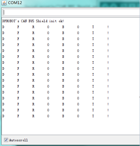
Receiver: output in the serial port
Basic CAN BUS Receiving and sending function(receive:interrupt mode)
In this section we will test basic CAN BUS receiving and sending functions in this experiment, but will only receive data by interrupt mode.
Connection Diagram

Sample Code
Receiver Code
/***********************************************************
  *demo: CAN-BUS Shield, receive data with interrupt mode
  * when in interrupt mode, the data coming can't be too fast, must >20ms, or else you can use check mode
  * Jansion, 2015-5-27
***********************************************************/
  #include <SPI.h>
  #include "df_can.h"

  const int SPI_CS_PIN = 10;
  MCPCAN CAN(SPI_CS_PIN);                                    // Set CS pin


  unsigned char flagRecv = 0;
  unsigned char len = 0;
  unsigned char buf[8];
  char str[20];

  void setup()
  {
      Serial.begin(115200);
      int count = 50;                                     // the max numbers of initializint the CAN-BUS, if initialize failed first!.
      do {
          CAN.init();   //must initialize the Can interface here!
          if(CAN_OK == CAN.begin(CAN_500KBPS))                   // init can bus : baudrate = 500k
          {
              Serial.println("DFROBOT's CAN BUS Shield init ok!");
              break;
          }
          else
          {
              Serial.println("DFROBOT's CAN BUS Shield init fail");
              Serial.println("Please Init CAN BUS Shield again");

              delay(100);
              if (count <= 1)
                  Serial.println("Please give up trying!, trying is useless!");
          }

      }while(count--);


      attachInterrupt(0, MCP2515_ISR, FALLING); // start interrupt
  }

  void MCP2515_ISR()
  {
      flagRecv = 1;
  }

  void loop()
  {
      if(flagRecv)
      {                                   // check if get data

          flagRecv = 0;                   // clear flag

          // iterate over all pending messages
          // If either the bus is saturated or the MCU is busy,
          // both RX buffers may be in use and after having read a single
          // message, MCU does  clear the corresponding IRQ conditon.
          while (CAN_MSGAVAIL == CAN.checkReceive())
          {
              // read data,  len: data length, buf: data buf
              CAN.readMsgBuf(&len, buf);

              // print the data
              for(int i = 0; i<len; i++)
              {
                  Serial.print(buf[i]);Serial.print("\t");
              }
              Serial.println();
          }
      }
  }
Sender code
  // demo: CAN-BUS Shield, send data
  #include <df_can.h>
  #include <SPI.h>

  const int SPI_CS_PIN = 10;

  MCPCAN CAN(SPI_CS_PIN);                                    // Set CS pin

  void setup()
  {
      Serial.begin(115200);
      int count = 50;                                     // the max numbers of initializint the CAN-BUS, if initialize failed first!.
      do {
          CAN.init();   //must initialize the Can interface here!
          if(CAN_OK == CAN.begin(CAN_500KBPS))                   // init can bus : baudrate = 500k
          {
              Serial.println("DFROBOT's CAN BUS Shield init ok!");
              break;
          }
          else
          {
              Serial.println("DFROBOT's CAN BUS Shield init fail");
              Serial.println("Please Init CAN BUS Shield again");

              delay(100);
              if (count <= 1)
                  Serial.println("Please give up trying!, trying is useless!");
          }

      }while(count--);

  }

  unsigned char data[8] = {'D', 'F', 'R', 'O', 'B', 'O', 'T', '!'};
  void loop()
  {
      // send data:  id = 0x06, standrad flame, data len = 8, data: data buf
      CAN.sendMsgBuf(0x06, 0, 8, data);
      delay(100);                       // send data per 100ms
  }
Result
Receiver: output in the serial port

Accecpted to specify the data frame of the ID(receive:interrupt mode)
This test is to specify the data frame of the ID when the CAN module is initialized. Data is received using interrupt mode.
Connection Diagram
 ](https://raw.githubusercontent.com/DFRobot/DFRobotMediaWikiImage/master/Image/DFR0370-TWO.png "DFR0370-TWO.png")
Sample Code
Receiver Code
/**************************************************************************************************************
   *demo: CAN-BUS Shield, receive data with interrupt mode, and set mask and filter
   * when in interrupt mode, the data coming can't be too fast, must >20ms, or else you can use check mode
   * Jansion, 2015-5-27
 ****************************************************************************************************************/
  #include <SPI.h>
  #include "df_can.h"
  const int SPI_CS_PIN = 10;
  MCPCAN CAN(SPI_CS_PIN);                                    // Set CS pin
  unsigned char flagRecv = 0;
  unsigned char len = 0;
  unsigned char buf[8];
  char str[20];
  void setup()
  {
      Serial.begin(115200);
      int count = 50;                                     // the max numbers of initializint the CAN-BUS, if initialize failed first!.

      do {
          CAN.init();   //must initialize the Can interface here!
          CAN.init_Mask(MCP_RXM0, 0, 0x3ff);                         // there are 2 mask in mcp2515, you need to set both of them
          CAN.init_Mask(MCP_RXM1, 0, 0x3ff);
          /*
           * set filter, we can receive id from 0x04 ~ 0x09 except for 0x06
           * // there are 6 filter in mcp2515,so it can filter six id,i.e.0x04~0x09.
           */
          CAN.init_Filter(MCP_RXF0, 0, 0x04);                         // filter 0 for id = 0x04
          CAN.init_Filter(MCP_RXF1, 0, 0x05);                         // filter 1 for id = 0x05
          // CAN.init_Filter(MCP_RXF2, 0, 0x06);                         // filter 2 for id = 0x06
          CAN.init_Filter(MCP_RXF3, 0, 0x07);                         // filter 3 for id = 0x07
          CAN.init_Filter(MCP_RXF4, 0, 0x08);                         // filter 4 for id = 0x08
          CAN.init_Filter(MCP_RXF5, 0, 0x09);                         // filter 5 for id = 0x09
          if(CAN_OK == CAN.begin(CAN_500KBPS))                   // init can bus : baudrate = 500k
          {
              Serial.println("DFROBOT's CAN BUS Shield init ok!");
              break;
          }
          else
          {
              Serial.println("DFROBOT's CAN BUS Shield init fail");
              Serial.println("Please Init CAN BUS Shield again");

              delay(100);
              if (count <= 1)
                  Serial.println("Please give up trying!, trying is useless!");
          }

      }while(count--);

      attachInterrupt(0, MCP2515_ISR, FALLING); // start interrupt


      /*
       * set mask, set both the mask to 0x3ff
       */

  }

  void MCP2515_ISR()
  {
      flagRecv = 1;
  }

  void loop()
  {
      if(flagRecv)                   // check if get data
      {

          flagRecv = 0;                // clear flag
          CAN.readMsgBuf(&len, buf);    // read data,  len: data length, buf: data buf

          Serial.println("\r\n------------------------------------------------------------------");
          Serial.print("Get Data From id: ");
          Serial.println(CAN.getCanId());
          for(int i = 0; i<len; i++)    // print the data
          {
              Serial.print("0x");
              Serial.print(buf[i], HEX);
              Serial.print("\t");
          }
          Serial.println();

      }
  }
Sender code
 /***************************************************************
  * demo: set_mask_filter_send
  * this demo will show you how to use mask and filter
  * Jansion, 2015-5-27
  *****************************************************************/
  #include <df_can.h>
  #include <SPI.h>
  const int SPI_CS_PIN = 10;
  MCPCAN CAN(SPI_CS_PIN);                                   // Set CS pin
  void setup()
  {
      Serial.begin(115200);
      int count = 50;                                     // the max numbers of initializint the CAN-BUS, if initialize failed first!.
      do {
          CAN.init();   //must initialize the Can interface here!
          if(CAN_OK == CAN.begin(CAN_500KBPS))                   // init can bus : baudrate = 500k
          {
              Serial.println("DFROBOT's CAN BUS Shield init ok!");
              break;
          }
          else
          {
              Serial.println("DFROBOT's CAN BUS Shield init fail");
              Serial.println("Please Init CAN BUS Shield again");

              delay(100);
              if (count <= 1)
                  Serial.println("Please give up trying!, trying is useless!");
          }

      }while(count--);
  }

  unsigned char data[8] = {'D', 'F', 'R', 'O', 'B', 'O', 'T', '!'};

  void loop()
  {
      for(int id=0; id<10; id++)
      {
          memset(data, id, sizeof(data));                 // set id to send data buff, id is arranged form 0x00 to 0x09.
          CAN.sendMsgBuf(id, 0, sizeof(data), data);
          delay(100);
      }
  }
Result
Receiver: output in the serial port
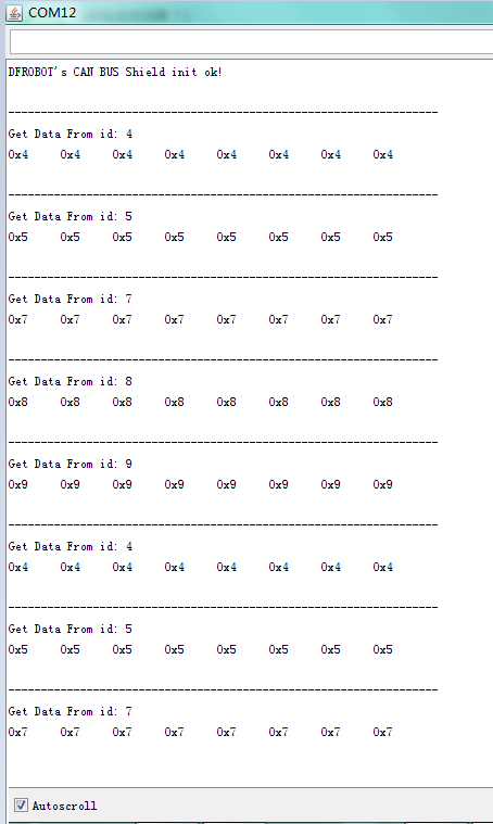
The received data frame has no data from ID 0x06,0x00,0x01 or 0x02 which not matched with the ID which is set by Data acceptance filter. This shows that the filter can be a single job, or a few filters working at the same time, or all of the filters working at the same time. When all filters are not in use then can receive any data.
Three modules of the network
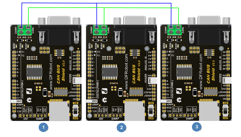
This tests all three modules on the network and the data transceiver situation. Each module of the three modules can be used as a receiver, and can also be used as a sender. 3 node devices are used in this experiment; node 1, node 2, node 3.
Node 1 is used only as a receiving node, which can receive data frame which ID is 0x04, 0x05,0x07,0x08 and 0x09.
Node 2 is used only to receive data frames form ID 0x09 and only send data form ID 0x08 which data frame is “node 2”.
Node 3 only receives data frames form ID 0x08 and only send data form ID 0x09 which data frame is “node 3”.
Connection Diagram
Sample Code
Node 1 Code
/**************************************************************************************************************
  *demo: CAN-BUS Shield, receive data with interrupt mode, and set mask and filter
  * when in interrupt mode, the data coming can't be too fast, must >20ms, or else you can use check mode
  * Jansion, 2015-5-27
****************************************************************************************************************/
  #include <SPI.h>
  #include "df_can.h"

  const int SPI_CS_PIN = 10;
  MCPCAN CAN(SPI_CS_PIN);                                    // Set CS pin
  unsigned char flagRecv = 0;
  unsigned char len = 0;
  unsigned char buf[8];
  char str[20];
  void setup()
  {
      Serial.begin(115200);
      int count = 50;                                     // the max numbers of initializint the CAN-BUS, if initialize failed first!.

      do {
          CAN.init();   //must initialize the Can interface here!
          CAN.init_Mask(MCP_RXM0, 0, 0x3ff);                         // there are 2 mask in mcp2515, you need to set both of them
          CAN.init_Mask(MCP_RXM1, 0, 0x3ff);
          /*
           * set filter, we can receive id from 0x04 ~ 0x09 except for 0x06
           * // there are 6 filter in mcp2515,so it can filter six id,i.e.0x04~0x09.
           */
          CAN.init_Filter(MCP_RXF0, 0, 0x04);                         // filter 0 for id = 0x04
          CAN.init_Filter(MCP_RXF1, 0, 0x05);                         // filter 1 for id = 0x05
          // CAN.init_Filter(MCP_RXF2, 0, 0x06);                         // filter 2 for id = 0x06
          CAN.init_Filter(MCP_RXF3, 0, 0x07);                         // filter 3 for id = 0x07
          CAN.init_Filter(MCP_RXF4, 0, 0x08);                         // filter 4 for id = 0x08
          CAN.init_Filter(MCP_RXF5, 0, 0x09);                         // filter 5 for id = 0x09
          if(CAN_OK == CAN.begin(CAN_500KBPS))                   // init can bus : baudrate = 500k
          {
              Serial.println("DFROBOT's CAN BUS Shield init ok!");
              break;
          }
          else
          {
              Serial.println("DFROBOT's CAN BUS Shield init fail");
              Serial.println("Please Init CAN BUS Shield again");

              delay(100);
              if (count <= 1)
                  Serial.println("Please give up trying!, trying is useless!");
          }

      }while(count--);

      attachInterrupt(0, MCP2515_ISR, FALLING); // start interrupt


      /*
       * set mask, set both the mask to 0x3ff
       */

  }

  void MCP2515_ISR()
  {
      flagRecv = 1;
  }

  void loop()
  {
      if(flagRecv)                   // check if get data
      {

          flagRecv = 0;                // clear flag
          CAN.readMsgBuf(&len, buf);    // read data,  len: data length, buf: data buf

          Serial.println("\r\n------------------------------------------------------------------");
          Serial.print("Get Data From id: ");
          Serial.println(CAN.getCanId());
          for(int i = 0; i<len; i++)    // print the data
          {
             Serial.print(buf[i]);
             Serial.print("\t");
          }
          Serial.println();

      }
  }
Node 2 code
#include <SPI.h>
   #include "df_can.h"

   const int SPI_CS_PIN = 10;
   MCPCAN CAN(SPI_CS_PIN);                                    // Set CS pin
   unsigned char flagRecv = 0;
   unsigned char len = 0;
   unsigned char buf[8];
   char str[20];
   void setup()
   {
     Serial.begin(115200);
     int count = 50;                                     // the max numbers of initializint the CAN-BUS, if initialize failed first!.

     do {
         CAN.init();   //must initialize the Can interface here!
         CAN.init_Mask(MCP_RXM0, 0, 0x3ff);                         // there are 2 mask in mcp2515, you need to set both of them
         CAN.init_Mask(MCP_RXM1, 0, 0x3ff);
         /*
          * set filter, we can receive id from 0x04 ~ 0x09 except for 0x06
          * // there are 6 filter in mcp2515,so it can filter six id,i.e.0x04~0x09.
          */
         CAN.init_Filter(MCP_RXF5, 0, 0x09);                         // filter 5 for id = 0x09
         if(CAN_OK == CAN.begin(CAN_500KBPS))                   // init can bus : baudrate = 500k
         {
             Serial.println("DFROBOT's CAN BUS Shield init ok!");
             break;
         }
         else
         {
             Serial.println("DFROBOT's CAN BUS Shield init fail");
             Serial.println("Please Init CAN BUS Shield again");

             delay(100);
             if (count <= 1)
                 Serial.println("Please give up trying!, trying is useless!");
         }

     }while(count--);

     attachInterrupt(0, MCP2515_ISR, FALLING); // start interrupt


     /*
      * set mask, set both the mask to 0x3ff
      */

   }

   void MCP2515_ISR()
   {
     flagRecv = 1;
   }


   unsigned char data[] = "node 2";
   void loop()
   {
     if(flagRecv)                   // check if get data
     {
         flagRecv = 0;                // clear flag
         CAN.readMsgBuf(&len, buf);    // read data,  len: data length, buf: data buf

         Serial.println("\r\n------------------------------------------------------------------");
         Serial.print("Get Data From id: ");
         Serial.println(CAN.getCanId());
         for(int i = 0; i<len; i++)    // print the data
         {

             Serial.print(buf[i]);
             Serial.print("\t");
         }
         Serial.println();
     }

     // send data:  id = 0x08, standrad flame, data len = 8, data: data buf
     CAN.sendMsgBuf(0x08, 0, sizeof(data), data);
     delay(1000);                       // send data per 100ms

   }
Node 3 code
 #include <SPI.h>
   #include "df_can.h"

   const int SPI_CS_PIN = 10;
   MCPCAN CAN(SPI_CS_PIN);                                    // Set CS pin
   unsigned char flagRecv = 0;
   unsigned char len = 0;
   unsigned char buf[8];
   char str[20];
   void setup()
   {
     Serial.begin(115200);
     int count = 50;                                     // the max numbers of initializint the CAN-BUS, if initialize failed first!.

     do {
         CAN.init();   //must initialize the Can interface here!
         CAN.init_Mask(MCP_RXM0, 0, 0x3ff);                         // there are 2 mask in mcp2515, you need to set both of them
         CAN.init_Mask(MCP_RXM1, 0, 0x3ff);
         /*
          * set filter, we can receive id from 0x04 ~ 0x09 except for 0x06
          * // there are 6 filter in mcp2515,so it can filter six id,i.e.0x04~0x09.
          */
         CAN.init_Filter(MCP_RXF5, 0, 0x08);                         // filter 5 for id = 0x09
         if(CAN_OK == CAN.begin(CAN_500KBPS))                   // init can bus : baudrate = 500k
         {
             Serial.println("DFROBOT's CAN BUS Shield init ok!");
             break;
         }
         else
         {
             Serial.println("DFROBOT's CAN BUS Shield init fail");
             Serial.println("Please Init CAN BUS Shield again");

             delay(100);
             if (count <= 1)
                 Serial.println("Please give up trying!, trying is useless!");
         }

     }while(count--);

     attachInterrupt(0, MCP2515_ISR, FALLING); // start interrupt


     /*
      * set mask, set both the mask to 0x3ff
      */

   }

   void MCP2515_ISR()
   {
     flagRecv = 1;
   }


   unsigned char data[] = "node 3";
   void loop()
   {
     if(flagRecv)                   // check if get data
     {
         flagRecv = 0;                // clear flag
         CAN.readMsgBuf(&len, buf);    // read data,  len: data length, buf: data buf

         Serial.println("\r\n------------------------------------------------------------------");
         Serial.print("Get Data From id: ");
         Serial.println(CAN.getCanId());
         for(int i = 0; i<len; i++)    // print the data
         {

             Serial.print(buf[i]);
             Serial.print("\t");
         }
         Serial.println();
     }

     // send data:  id = 0x08, standrad flame, data len = 8, data: data buf
     CAN.sendMsgBuf(0x09, 0, sizeof(data), data);
     delay(1000);                       // send data per 100ms

   }
Result
Output in the each serial port

COM10 is running Node 3 code, which only receives the ID 0x08 data frame. COM12 is running Node 2 code, which only receives the ID 0x09 data frame. COM21 is running Node 1 code, which receives the ID 0x09 and 0x08 data frame.
SD CARD Read and Write
The purpose of this experimental is receiving node receives the ten data from the sending node.And then put it into the SD card.Finally read it from SD card out and print it out through the serial port.
Connection Diagram

Sample Code
Receiver Code
 /**************************************************************************************************************
 *demo: CAN-BUS Shield, receive data with interrupt mode, and set mask and filter
 * when in interrupt mode, the data coming can't be too fast, must >20ms, or else you can use check mode
 * Jansion, 2015-5-27
 ****************************************************************************************************************/
#include <SPI.h>
#include "df_can.h"
#include <SD.h>

const int SPI_CS_PIN = 10;
MCPCAN CAN(SPI_CS_PIN);                                    // Set CS pin
unsigned char flagRecv = 0;
unsigned char len = 0;
unsigned char buf[8];
char str[20];
char  sd_cspin = 4; //pin 4 as spi_cs pin
File myFile;

void setup()
{
    Serial.begin(115200);
    int count = 50;                                     // the max numbers of initializint the CAN-BUS, if initialize failed first!.
    Serial.print("Initializing can controlor...");
    do {
        CAN.init();   //must initialize the Can interface here!
        CAN.init_Mask(MCP_RXM0, 0, 0x3ff);                         // there are 2 mask in mcp2515, you need to set both of them
        CAN.init_Mask(MCP_RXM1, 0, 0x3ff);
        /*
         * set filter, we can receive id from 0x04 ~ 0x09 except for 0x06
         * // there are 6 filter in mcp2515,so it can filter six id,i.e.0x04~0x09.
         */
        CAN.init_Filter(MCP_RXF0, 0, 0x04);                         // filter 0 for id = 0x04
        CAN.init_Filter(MCP_RXF1, 0, 0x05);                         // filter 1 for id = 0x05
        CAN.init_Filter(MCP_RXF2, 0, 0x60);                         // filter 2 for id = 0x60
        CAN.init_Filter(MCP_RXF3, 0, 0x07);                         // filter 3 for id = 0x07
        CAN.init_Filter(MCP_RXF4, 0, 0x08);                         // filter 4 for id = 0x08
        CAN.init_Filter(MCP_RXF5, 0, 0x09);                         // filter 5 for id = 0x09
        if(CAN_OK == CAN.begin(CAN_500KBPS))                   // init can bus : baudrate = 500k
        {
            Serial.println("DFROBOT's CAN BUS Shield init ok!");
            break;
        }
        else
        {
            Serial.println("DFROBOT's CAN BUS Shield init fail");
            Serial.println("Please Init CAN BUS Shield again");

            delay(100);
            if (count <= 1)
                Serial.println("Please give up trying!, trying is useless!");
        }

    }while(count--);

    attachInterrupt(0, MCP2515_ISR, FALLING); // start interrupt

    Serial.print("Initializing SD card...");

    if (!SD.begin(sd_cspin)) {
        Serial.println("initialization failed!");
        return;
    }
    Serial.println("initialization success!");
    myFile = SD.open("Node0x60.txt", FILE_WRITE); //the file named Node0x60.txt use to save the data
    // with the frame id equeling 0x06.
    if (!myFile)
    {
        Serial.println("open Node0x60.text failed!");


    }
    else
    {
        Serial.println("open Node0x60.text success!");
    }
    /*
     * set mask, set both the mask to 0x3ff
     */

}

void MCP2515_ISR()
{
    flagRecv = 1;
}
char filewrite = 1, fileread = 0;
int i = 0, j = 0;
void loop()
{

    if(flagRecv)                   // check if get data
    {
        flagRecv = 0;                // clear flag
        CAN.readMsgBuf(&len, buf);    // read data,  len: data length, buf: data buf
        if (filewrite)
        {
            if (i++ < 1) //only recieve one frame
            {
                myFile.write(buf, len);
            }
            else
            {
                myFile.close();
                filewrite = 0;
                myFile = SD.open("Node0x60.txt", FILE_WRITE);
                if (SD.exists("Node0x60.txt")) {
                    Serial.println("example.txt exists.");
                    fileread = 1;
                }
                else {
                    Serial.println("example.txt doesn't exist.");
                }
            }
        }
        if (fileread)
        {
            Serial.println("printf the data that myFile has saved! ");
            myFile.read(buf, len);
            Serial.println((char *)buf);
            Serial.println("");
            myFile.close();

            Serial.println("myFile closed!!!!");
            fileread = 0;
        }

    }
}
Sender Code
 // demo: CAN-BUS Shield, send data
  #include <df_can.h>
  #include <SPI.h>

  const int SPI_CS_PIN = 10;

  MCPCAN CAN(SPI_CS_PIN);                                    // Set CS pin

  void setup()
  {
      Serial.begin(115200);
      int count = 50;                                     // the max numbers of initializint the CAN-BUS, if initialize failed first!.
      do {
          CAN.init();   //must initialize the Can interface here!
          if(CAN_OK == CAN.begin(CAN_500KBPS))                   // init can bus : baudrate = 500k
          {
              Serial.println("DFROBOT's CAN BUS Shield init ok!");
              break;
          }
          else
          {
              Serial.println("DFROBOT's CAN BUS Shield init fail");
              Serial.println("Please Init CAN BUS Shield again");

              delay(100);
              if (count <= 1)
                  Serial.println("Please give up trying!, trying is useless!");
          }

      }while(count--);

  }

  unsigned char data[8] = {'D', 'F', 'R', 'O', 'B', 'O', 'T', '!'};
  void loop()
  {
      // send data:  id = 0x60, standrad flame, data len = 8, data: data buf
      CAN.sendMsgBuf(0x60, 0, 8, data);
      delay(1000);                       // send data per 100ms
  }
Result
Receiver: output in the serial port
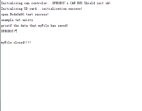
Experimental phenomenon analysis: the receiving node receives the data frame from ID 0x60, and deposits it in a file named Node0x60.text file. Then it closes the file. Finally, it opens the file, and reads the data and prints it through the serial port.
Protocol/Library Explanation
FAQ
There are no questions about this product yet. If you have any problems or suggestions, you are welcome to email us or post on the DFRobot forum!
For any questions/advice/cool ideas to share, please visit the DFRobot Forum or email [email protected]
