DFRduino M0 Mainboard
SKU: DFR0392
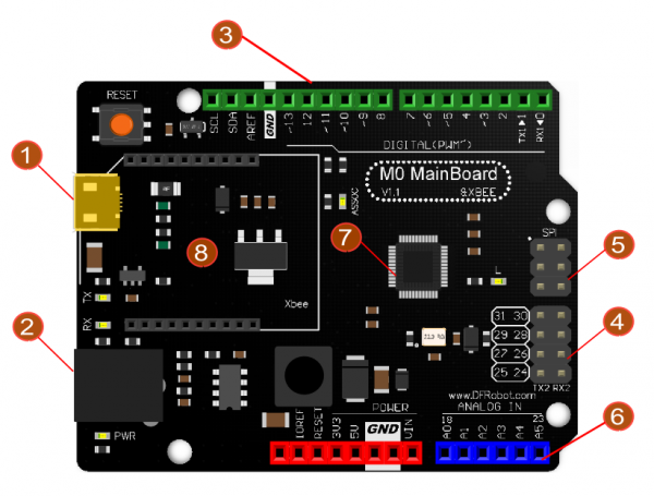
The DFRduino M0 Mainboard is a high-performance Arduino-compatible board featuring ARM Cortex-M0 architecture, supporting 5V logic levels, equipped with 31 digital pins, 6 analog pins, and an IIS interface for HIFI audio capabilities. Unlike traditional boards, DFRduino M0 addresses common limitations such as pin scarcity and compatibility issues, making it an ideal choice for advanced projects. It requires independent IDE board installation and is compatible with Windows, Linux, and MAC platforms, supporting IDE versions 1.6.0 and above, with custom settings available for other versions.