Introduction

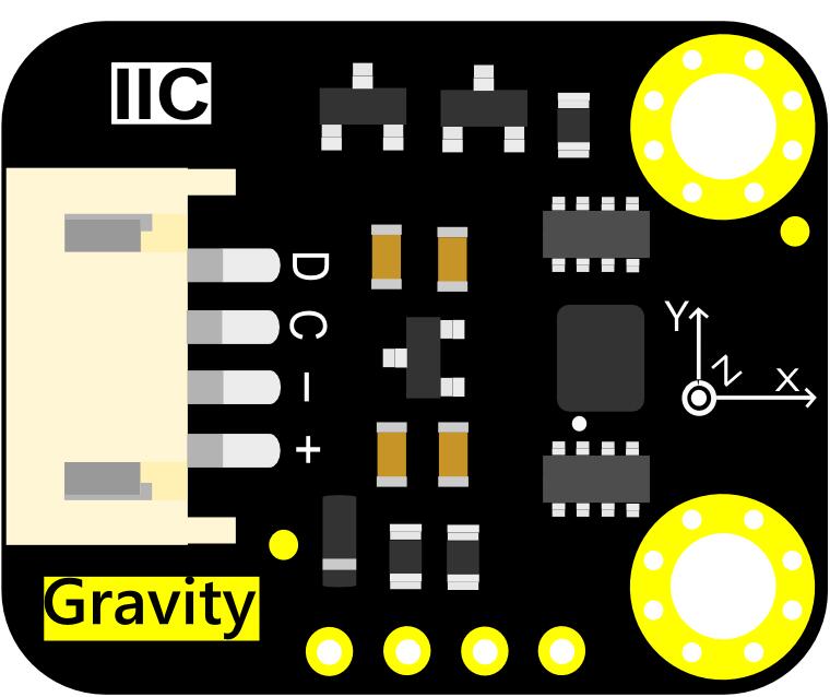
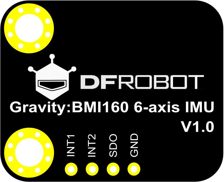
The BMI160 6-axis inertial motion sensor is a new product from DFRobot. It is based on Bosch BMI160 6-axis MEMS sensor which integrates 16-bit 3-axis accelerometer with ultra-low-power 3-axis gyroscope. Bosch BMI160 is designed for smartphones, tablets, wearable devices. It has built-in intelligent step-counting algorithms that can be read directly through registers. Built-in 3-axis acceleration and 3-axis gyroscope can detect running, fitness and other motion. Built-in LDO power management chip, supports 3.2~6V wide voltage power supply, and also has I2C level conversion circuit, compatible with Arduino 3.3V and 5V micro controller.

Application Scenarios

  • Step Count
  • Acceleration Detection
  • Inclination Measurement
  • Display Toggle Horizontal / Vertical Mode

Specifications

  • Operating Voltage: 3.2V~6V
  • Current Consumption: <1mA
  • Interface: Gravity-IIC
  • Acceleration Range: ±2g/±4g/±8g/±16g
  • Gyroscopes Range: ±125°/s,±250°/s,±500°/s,±1000°/s,±2000°/s
  • Acceleration Zero-g Offset: ±40mg
  • Gyroscopes Zero-g Offset: ±10°/s
  • Programmable Frequency: 25/32Hz~1600Hz
  • 6D Detection and Location
  • 16-bit Data Output
  • Shock Resistance: 1000gx 200us
  • 2 Independent Programmable Interrupt Generators
  • In-built 1024 Byte FIFO
  • Working Temperature:-40℃~ 85℃
  • Dimension: 22X27mm/0.87x1.06 in

Appearance and Size Chart

Label Name Function
+ VCC 3.2~6V
- GND GND
C SCL I2C-SCL
D SDA I2C-SDA
INT1 INT1 Configurable interrupt output 1
INT2 INT2 Configurable interrupt output 2
SDO SDO Choose the address of I2C [GND: 0x68 VCC: 0x69 (Default)]

BMI160 6-Axis IMU Sensor Pin Description

Hardware

Hardware Preparation

  • 1 x BMI160 6-axis IMU
  • 1 x Arduino Uno

Hardware Connection

  • Connect the BMI160 6-axis IMU to Arduino board by I2C (" "can connect "3V3" or "5V")
  • Connect the INT1 or INT2 to the corresponding pins on the Arduino board, as shown in the following table
Arduino board Corresponding Pins
Arduino UNO D2
FireBeetle-ESP32 D13
FireBeetle-ESP8266 D13
FireBeetle-Board328P D2
Leonardo D3

Connection Diagram Arduino UNO-BMI160 6-Axis IMU Sensor

Examples

Step Count

Note:I2C has two addresses: 0x69 (Default, Vacant); 0x68 (Connect SDO to GND).
  • Tip: The pedometer algorithm does not recognize steps until after seven consecutive steps, and then if you stop walking at a certain time for too long, the counter will reset,it is also applies to INT1, INT2.
  • Note: At some point there is a discrepancy between the number of steps and the actual number of steps, due to the problem of the BMI chip itself."
#include <DFRobot_BMI160.h>

DFRobot_BMI160 bmi160;
const int8_t i2c_addr = 0x69;
bool readStep = false;

#if defined ARDUINO_AVR_UNO || defined ARDUINO_AVR_MEGA2560 || defined ARDUINO_AVR_PRO
  //interrupt number of uno and mega2560 is 0
  int pbIn = 2;
#elif ARDUINO_AVR_LEONARDO
  //interrupt number of uno and leonardo is 0
  int pbIn = 3;
#else
  int pbIn = 13;
#endif
/*the bmi160 have two interrput interfaces*/
int int1 = 1;
int int2 = 2;

void stepChange()
{
  //once the step conter is changed, the value can be read
  readStep = true;
}

void setup(){
  Serial.begin(115200);
  delay(100);

  //set and init the bmi160 i2c address
  while (bmi160.I2cInit(i2c_addr) != BMI160_OK){
    Serial.println("i2c init fail");
    delay(1000);
  }

  //set interrput number to int1 or int2
  if (bmi160.setInt(int1) != BMI160_OK){
    Serial.println("set interrput fail");
    while(1);
  }

  //set the bmi160 mode to step counter
  if (bmi160.setStepCounter() != BMI160_OK){
    Serial.println("set step fail");
    while(1);
  }
#if defined ARDUINO_AVR_UNO || defined ARDUINO_AVR_MEGA2560 || defined ARDUINO_AVR_LEONARDO || defined ARDUINO_AVR_PRO
  //set the pin in the board to connect to int1 or int2 of bmi160
  attachInterrupt(digitalPinToInterrupt(pbIn), stepChange, FALLING);
#else
  attachInterrupt(pbIn, stepChange, FALLING);
#endif
}

void loop(){
  if (readStep){
    uint16_t stepCounter = 0;
    //read step counter from hardware bmi160
    if (bmi160.readStepCounter(&stepCounter)==BMI160_OK){
      Serial.print("step counter = ");Serial.println(stepCounter);
    }
    readStep = false;
  }
}

Acceleration Gyroscope

  • Fig2: Gravity:BMI160 6-axis IMU Acceleration Gyroscope
  • Tip:The first three columns are the data of the gyroscope in the direction of the X, Y, and Z axis, and the last three are the data of the acceleration in the direction of the X, Y, and Z axis.
#include "DFRobot_BMI160.h"

DFRobot_BMI160 bmi160;
const int8_t i2c_addr = 0x69;
void setup(){
  Serial.begin(115200);
  delay(100);

  //init the hardware bmin160
  if (bmi160.softReset() != BMI160_OK){
    Serial.println("reset false");
    while(1);
  }

  //set and init the bmi160 i2c address
  if (bmi160.I2cInit(i2c_addr) != BMI160_OK){
    Serial.println("init false");
    while(1);
  }
}

void loop(){
  int i = 0;
  int rslt;
  int16_t accelGyro[6]={0};

  //get both accel and gyro data from bmi160
  //parameter accelGyro is the pointer to store the data
  rslt = bmi160.getAccelGyroData(accelGyro);
  if(rslt == 0){
    for(i=0;i<6;i  ){
      if (i<3){
        //the first three are gyro datas
        Serial.print(accelGyro[i]*3.14/180.0);Serial.print("\t");
      }else{
        //the following three data are accel datas
        Serial.print(accelGyro[i]/16384.0);Serial.print("\t");
      }
    }
    Serial.println();
  }else{
    Serial.println("err");
  }
}

FAQ

For any questions, advice or cool ideas to share, please visit the DFRobot Forum.

More Documents

FAQ

For any questions, advice or cool ideas to share, please visit the DFRobot Forum.