Introduction
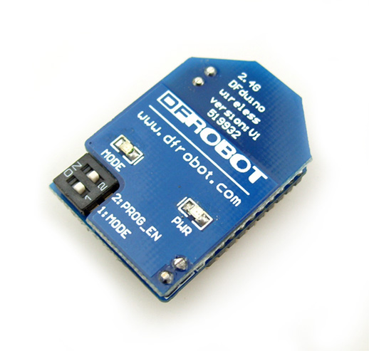
The wireless programming module (WPM) is designed for wireless upload skectch/codes to Arduino. With up-to 5 meters range, you can bring your laptop and do a wireless programming for your already deployed Arduino based devices which is hard to open. Cut the wire, and try this superb communication module.
This module can also be used as a standard bidirectional wireless communication module with up to 20 meters range and 115200 bps speed(line in sight). When uses as communication modules, it exchanges data as a transparent serial port. Only Tx/Rx will be required to do the transmission.
- Suitable for outdoor Arduino based devices.
- Suitable for Arduino based robots.
- Suitable for thoese devices which are hard to reach.
Specification
- Supply Voltage:3.3V
- Working current: 10mA
- Working Temperature: 0 - 70 C
- Interface: UART (TTL)
- Support Baud Rate:1200/2400/4800/9600/14400/19200/28800/38400/57600/115200
- Communication Range: 20 Meters (line in sight)
- Programming Range: 5 Meters (line in sight)
- Frequency Band:2.4-2.5GHz adjustable by 0.00008GHz
- Air Rate:250kbps/1M/2M
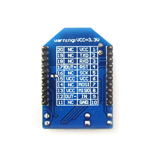
Pin Out Diagram
Configuration Tools
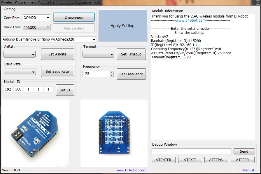
The configuration tools can be used to configure the Wireless Programming Module(WPM).
- Step 0:Set the two switches of the WPM
- Switch the WPM to config mode by switching the "Mode" to "ON" position, a blue (or red, depending on WPM Version) LED should turn on;
- Make sure the "Prog_EN" is at "ON" position.
- Step 1:Plug the WPM on the XBee Adapter
- Step 2:Connect the Xbee Adapter(V2) to the USB port of your PC via MINI USB Cable
- Step 3:Run the configuration tools on Windows.
- Step 4:Select the right serial port and baud rate (115200bps by default)
- If you do not know the baud rate, you might have to try different ones until you get a response on the right information window
- Step 5:Click button "Connect WPM",if everything is fine, the module information will be displayed in the right information window
- If you get no response try pressing the "ATENTER" and "Send" buttons on the lower right debug window
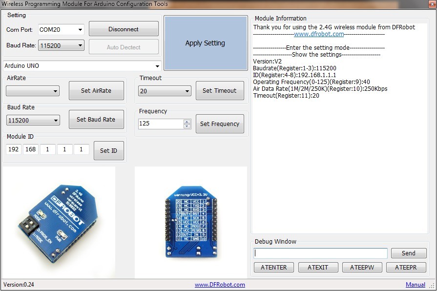
- Step 6:Select the proper Arduino board that you are intending to program.
- Step 7:Click "Apply Setting" button
- Step 8:Wait for the module to restart, once the module information(in the right window) has changed, the module is ready to do wireless programming
Application with an Arduino board
1.When using WPMs to upload code for your remote Arduino processor,you need a pair of this module.
2.As the Arduino board does not have to connect with PC, so do not forget external power supply, such as some batteries.
Setting for the WPM
- Step 1:Please first set the two WPMs according to the Configuration steps mentioned above.
- Step 2:(Set Both WPMs first.)
- Close the software.
- Make sure to switch the "Mode" to "OFF" position.
- The "PROG_EN" switch should still at "ON" position.
- Step 3:Plug one WPM on the XBee Adapter and another on an IO Expansion Shield or Xbee shield for Arduino.
- Step 4:Stack the IO Expansion Shield on the Arduino board(Use UNO as an example.)
- Step 5:Connect the USB Adapter to your PC, and choose the right com port in the Arduino IDE.
- Step 6:Open Arduino program in the Arduino IDE and press "upload".Then the "LINK" light will blink if the communication is successful on the WPMs.
Test Code
Upload this code into the UNO board when the configuration and connection have been finished.
const int ledPin =  13;      // the number of the LED pin

// Variables will change:
int ledState = LOW;             // ledState used to set the LED
long previousMillis = 0;        // will store last time LED was updated

long interval = 1000;           // interval at which to blink (milliseconds)

void setup() {
  // set the digital pin as output:
  pinMode(ledPin, OUTPUT);
}

void loop()
{
  unsigned long currentMillis = millis();

  if(currentMillis - previousMillis > interval) {
    // save the last time you blinked the LED
    previousMillis = currentMillis;

    // if the LED is off turn it on and vice-versa:
    if (ledState == LOW)
      ledState = HIGH;
    else
      ledState = LOW;

    // set the LED with the ledState of the variable:
    digitalWrite(ledPin, ledState);
  }
}
Compatibility
- DFRduino Duemilanove 328 (SKU:DFR0001)
- DFRduino Mega (SKU:DFR0003)
- Arduino Nano 328 (SKU: DFR0010)
- DFrduino FIO (SKU: DFR0069)
- DFRduino Romeo-All in one Controller (SKU:DFR0004)
- Arduino Uno
- Arduino Duemilanove or Nano w/ ATmeg328
- Arduino Diecimila,Duemilanove,or Nano w/ ATmega168
- Arduino Mega (ATmega1280)
- Arduino Mini
- Arduino Fio
- Arduino BT w/ ATmega328/168
- LilyPad Arduino w/ ATmega328/168
- Arduino Pro or Pro Mini (5V,16MHz) w/ ATmega328/168
- Arduino Pro or Pro Mini (3.3V,8MHz) w/ ATmega328/168
- Arduino NG or older w/ ATmega168/ATmega 8
NOTE: This module is not compatible with Mega 2560
。
Appendix
Register
The WPM has a 11 registers to hold parameters.
| Register Address | Name |
|---|---|
| 1 | Baud Rate |
| 2 | Baud Rate |
| 3 | Baud Rate |
| 4 | Address Register |
| 5 | Address Register |
| 6 | Address Register |
| 7 | Address Register |
| 8 | Address Register |
| 9 | Frequency Register |
| 10 | Air Rate Register |
| 11 | Timeout Register |
Advanced Settings
To program various Arduino boards, the baud rate need to be set to match the proper Arduino board before wireless programming.
For example, the Arduino UNO has 115200bps programming baud rate while the Arduino Mega 1280 has 57600bps programming baud rate.
| Arduino Model | Baud Rate | Timeout |
|---|---|---|
| Arduino Uno | 115200 | 20 |
| Arduino Duemilanove or Nano w/ ATmeg328 | 57600 | 20 |
| Arduino Diecimila,Duemilanove,or Nano w/ ATmega168 | 19200 | 10 |
| Arduino Mega (ATmega1280) | 57600 | 20 |
| Arduino Mini | 19200 | 10 |
| Arduino Fio | 57600 | 20 |
| Arduino BT w/ ATmega328 | 19200 | 10 |
| Arduino BT w/ ATmega168 | 19200 | 10 |
| LilyPad Arduino w/ ATmega328 | 57600 | 20 |
| LilyPad Arduino w/ ATmega168 | 19200 | 10 |
| Arduino Pro or Pro Mini (5V,16MHz) w/ ATmega328 | 57600 | 20 |
| Arduino Pro or Pro Mini (5V,16MHz) w/ ATmega168 | 19200 | 10 |
| Arduino Pro or Pro Mini (3.3V,8MHz) w/ ATmega328 | 57600 | 20 |
| Arduino Pro or Pro Mini (3.3V,8MHz) w/ ATmega168 | 19200 | 10 |
| Arduino NG or older w/ ATmega168 | 19200 | 10 |
| Arduino NG or older w/ ATmega8 | 19200 | 10 |
Commands
- ATENTER\r\n
Function: Display the module setting
- Example:
-
''Send:ATENTER\r\n
-
Return:
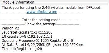
- ATEXIT\r\n
Function:Apply the change and reset the module
- Example:
-
Send:ATEXIT\r\n
-
Return:NONE
- ATEEPW[],[]\r\n
Function:Write value to EEPROM
- Example:Set the baud rate to 9600bps
-
Send:ATEEPW1,0\r\n
-
Send:ATEEPW2,96\r\n
-
Send:ATEEPW3,0\r\n
-
Return:NONE
- Example:Set the baud rate to 57600bps
-
Send:ATEEPW1,05\r\n
-
Send:ATEEPW2,76\r\n
-
Send:ATEEPW3,0\r\n
-
Return:NONE
- Example:Set the Air Rate to 1M
-
''Send:ATEEPW10,1\r\n
- Example:Set the Operating Frequency to 2.44GHz
-
Send:ATEEPW9,50\r\n
-
Return:NONE
- Example:Set the Time out to 20ms
-
Send:ATEEPW11,20\r\n
-
Return:NONE
- ATEEPR[]\r\n
Function:Read value from EEPROM
- Example:Read Timeout value
-
Send:ATEEPR11\r\n
-
Return:20
FAQ
| Q&A | Some general Arduino Problems/FAQ/Tips |
|---|---|
| A | For any questions, advice or cool ideas to share, please visit the DFRobot Forum. |
More
 Get Wireless Programming Module for Arduino from DFRobot Store or DFRobot Distributor.