
Introduction
DFRobot FireBeetle series are low power consumption micro-controllers specially designed for Internet of Things (IoT), and mainly focusing on fast and convenient low-power building.
FireBeetle LoRa 868MHz wireless transmission module adopts a high-performance SX1276 LoRa 868MHz chip and with built-in PA (power amplifier) gain, compatible with Aruino. It supports long-range monitor and FSK modulation. The maximum transmission rate of the module can reach up to 300Kbps. The module also supports LoRaTM and can provide a maximum transmission of 37.5Kbps. The circuit current is even lower than 0.2uA in the sleep mode. It can be widely used in remote home automation detection, health monitoring, wearable device and so on.
 NOTE: All parameters related to wireless signals in the same network should maintain consistency to avoid communication problems.
Specification
- Operating Voltage: 3.3V
- Operating Frequency: 868MHz
- Modulation: LoRaTM, FSK, GFSK, OOK
- Output Power: ≤20dBm
- Receiving Sensitivity: -139dBm@Lora
- Emission Current: ≤120mA
- Receiving Current: ≤15mA
- Sleep Current: ≤0.2uA
- Transmission Power Range: -1dBm~20dBm(Max)
- Transmission Mode: FIFO/ DMA
- Operating Frequency Range: 800MHz~900MHz(Typical value: 868MHz)
- Transmission Distance: 5Km
- Data Transmission Rate: @FSK,1.2~300Kbps @LoRaTM,0.018~37.5Kbps
- Built-in Antenna for Electrostatic Protection
- Maximum RSSI: 127dB
- FIFO Volume: 256bytes
- Support CRC Frequency-hopping
- SPI Interface
- GPIO Interface: 5 (can be used as interruption)
- Operating Temperature: -20℃~+70℃
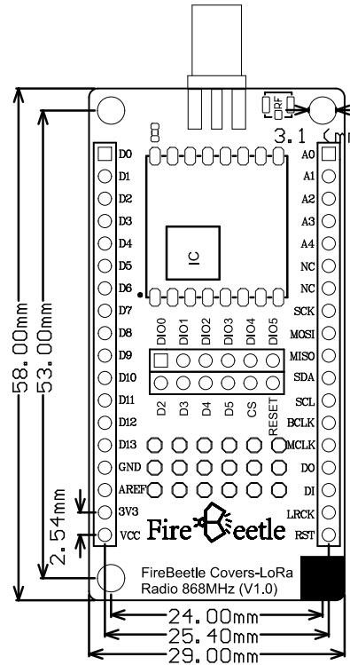
- Product Dimension: 58 x 29 mm/2.28x 1.14”
- Mounting Hole Dimension: 3.1mm(inner diameter)
Pinout
FireBeetle Covers-LoRa Radio 868MHz mainly communicates via SPI interface(MISO, MOSI, SCK, CS, RESET), and couples these control ports to the SPI interfece(MISO, MOSI, SCK) on the FireBettle mainboard. CS(chip-select) and RESET are connected to D2, D3, D4, D5 by DuPont wires.
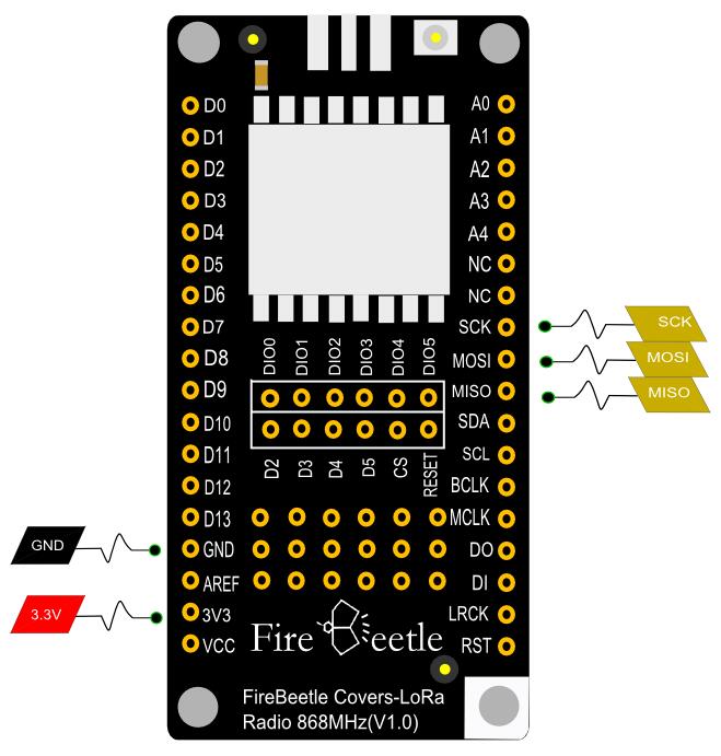
 NOTE: NC should not be connected, and VCC output as supply voltage(USB power supply: 5V, Lithium power supply: 3.7V)
Tutorial
Preparation
- Hardware
- ESP32 Board x2
- FireBeetle Covers-LoRa Radio 868MHz Module x2
- Conectors
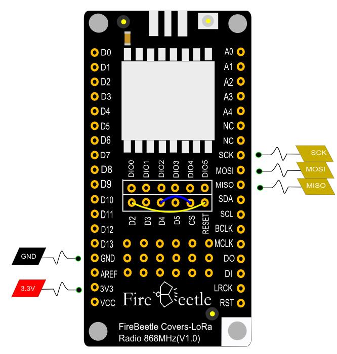
Generally, the default connection is CS to D4, RESET to D2. Of course you may revise program to change the default connection.(To transmit parameters through init funcion: init(uint8_t NSSPin = NSS_PIN, uint8_t NRESETPin = RESET_PIN)
- Software
Arduino IDE, click to download Arduino IDE(Please select verison acoording to the actual application)
Connection
- Piece together ESP32 Board and LoRa module
- Connect ESP32 Board to PC via USB
Sample Code
Download FireBeele Covers-LoRa Radio 868MHz Library first. [How to install library files?](https://docs.arduino.cc/software/ide-v1/tutorials/installing-libraries#.UxU8mdzF9H0"How to install library files?")
- Download master-slave programs to two ESP32 boards
- Slave Program code
/*!
 * @file receiverTest.ino
 * @brief DFRobot's received data
 * @n [Get the module here]
 * @n This example is receive.
 * @n [Connection and Diagram]
 *
 * @copyright	[DFRobot](https://www.dfrobot.com), 2016
 * @copyright	GNU Lesser General Public License
 *
 * @author [yangyang]
 * @version  V1.0
 * @date  2017-04-10
 */
#include <DFRobot_LoRa.h>

DFRobot_LoRa lora;

uint8_t len;
uint8_t rxBuf[32];

void setup()
{
	Serial.begin(115200);

	pinMode(LED_BUILTIN, OUTPUT);
	Serial.println("Receiver Test");
        //init(uint8_t NSSPin = NSS_PIN, uint8_t NRESETPin = RESET_PIN)
	if(!lora.init()) {
		Serial.println("Starting LoRa failed!");
		while (1);
	}

	lora.rxInit();
}
void loop()
{
	if(lora.waitIrq()) {   // wait for RXDONE interrupt
		lora.clearIRQFlags();
		len = lora.receivePackage(rxBuf);  // receive data
		Serial.write(rxBuf, len);
		Serial.println();
		lora.rxInit();    // wait for packet from master

		// print RSSI of packet
    	Serial.print("with RSSI ");
    	Serial.println(lora.readRSSI());

		static uint8_t i;
		i = ~i;
		digitalWrite(LED_BUILTIN, i);
	}
}
- Master Program code
/*!
 * @file sendTest.ino
 * @brief DFRobot's send data
 * @n [Get the module here]
 * @n This example is send.
 * @n [Connection and Diagram]
 *
 * @copyright	[DFRobot](https://www.dfrobot.com), 2016
 * @copyright	GNU Lesser General Public License
 *
 * @author [yangyang]
 * @version  V1.0
 * @date  2017-04-10
 */

#include <DFRobot_LoRa.h>

DFRobot_LoRa lora;

uint8_t counter = 0;
uint8_t sendBuf[] = "HelloWorld!";

/* The default pin:
/		SS:D2
/		RST:D3
*/

void setup()
{
	Serial.begin(115200);
	//init(uint8_t NSSPin = NSS_PIN, uint8_t NRESETPin = RESET_PIN)
	if(!lora.init()) {
		Serial.println("Starting LoRa failed!");
		while (1);
	}
}
void loop()
{
	Serial.print("Sending packet: ");
	Serial.println(counter);

	// send packet
	lora.sendPackage(sendBuf, sizeof(sendBuf)); // sending data
	lora.idle();    // turn to standby mode

	counter++;
#if 0
	if(counter%10 == 0) {
		lora.sleep();
		delay (5000);// sleep 5 seconds
	}
#endif

	delay(500);
}
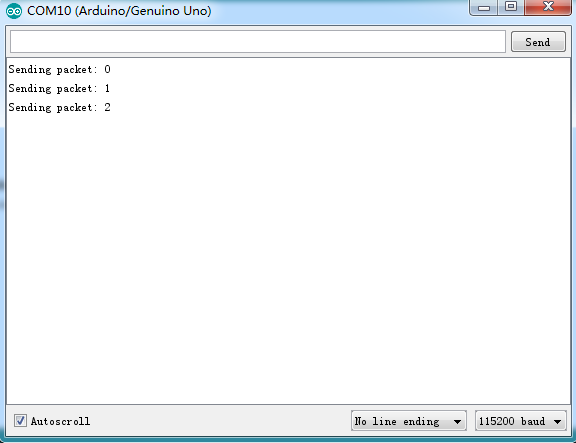
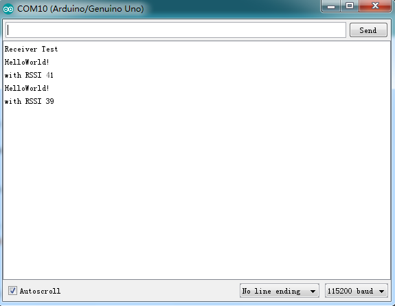
Result
Dimension Diagram
- Pin Sapce: 2.54mm
- Mounting Hole Sapce: 24mm/53mm
- Mounting Hole Dimension: 3.1mm
- Board Dimension: 29.00mm×58.00mm
- Thickness: 1.6mm
FAQ
| A | For any questions, advice or cool ideas to share, please visit the DFRobot Forum. |