Introduction
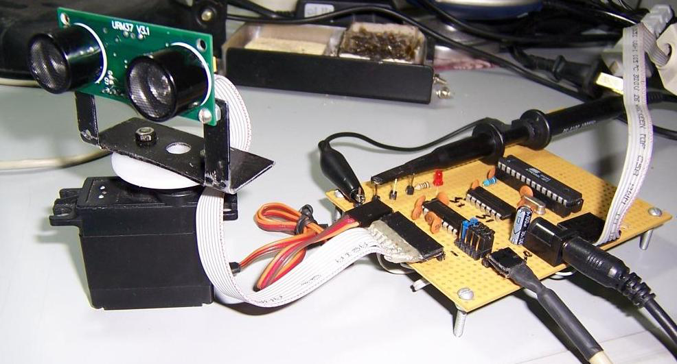
URM37 V5.0 is a powerful ultrasonic sensor mudule with bulit-in temperature compensation to ensure accurate distance measurement in the scene of temperature-changing applications. It has rich interface and offers various output: analog output, switch, serial (TTL and RS232 level optional), PWM and so on. The module can be used to measure the rotation angle of the servo. Connected with an external servo, it changes into a spatial ultrasonic scanner. URM37 has been on the market for many years and plays an important role in various fields, and we are constantly optimizing and improving it. The mechanical size, pin interface and communication commands of this version(V5.0)are compatible with older versions. Based on the old version, the following improvements have been made:
- The range has been increased from 5-500cm to 2-800cm
- The ranging performance is very stable at the voltage range of 3.3V~5.5V.
Caution: This ultrasonic sensor possesses a heightened sensitivity, and as such, may present inaccurate readings in complex environments or low-lying areas. To guarantee the precision of measurements, we suggest utilizing this sensor in an open environment, such as an outdoor setting.
Specification
- Operating Voltage: 3.3V~ 5.5V
- Operating Current: 20mA
- Working temperature: -10℃~ 70℃
- Detecting range: 2cm-800cm(ultimate range 1000cm)
- Resolution: 1cm
- Accuracy:1%
- Measuring Period: <100ms(Max)
- Dimensions: 22mm × 51 mm
- Weight: about 25g
Technical Descriptions
- Out of the use of a better ranging method, the measurement distance is further and more stable. if there is a need for customization, please contact the company.
- The module uses RS232 serial port for higher reliability, and the data can be collected through the computer serial port, which is very convenient to write communication programs.
- Serial level selected from the skipped stitches to button, user can easily select RS232 or TTL-level output level output by pressing the settings( after reboot ).
- The measured distance can be output via PWM, which eases the use process of the module.
- Pre-set a comparative value for the module, under the mode of automatic measurement, if the measured distance value is smaller than the pre-set value, the pin COMP/Trig will output a low level. In this way, this module can be used as an ultrasonic proximity switch.
- The module is equipped with the funciton of servo controlling. Under the mode of non-automatic measurement, it can combine with a servo into a 180° measuring module to scan the obstacles at the range of 0~180°.
- The module has a 123 bytes of EEPROM to memory whose values are kept when the board is turned off.
- The built-in temperature compensation circuit of the module is able to increase the accurary of the measurement.
- The module has a bulit-in temperature measurement component to read the environmental temperature with a resolution of 0.1℃.
- Power reverse protection
- Automatic measurement of time interval can be modified.
- Analog voltage output, voltage and the measured distance is proportional.
Pinout
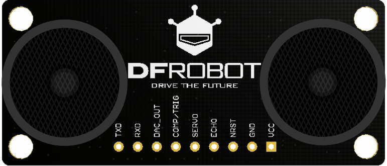
| Num | Label | Description |
|---|---|---|
| 1 | VCC | Power input (3.3V-5.5V) |
| 2 | GND | Ground |
| 3 | NRST | Reset |
| 4 | ECHO | Measured distance presented by the Data Output 0-25000US by PWM pulse width, 1 CM / 50US representative |
| 5 | SERVO | Servo Control Pin |
| 6 | COMP/TRIG | COMP:On/OFF mode, when the detected distance is smaller than a pre-set value, this pin pulls low./TRIG:PWM mode trigger input |
| 7 | DAC_OUT | Analog voltage output; the voltage is proportional to the distance |
| 8 | RXD | Asynchronous communication module data receiving pin: RS232/TTL level |
| 9 | TXD | Asynchronous communication module data receiving pin: RS232/TTL level |
Tutorial
The functions of URM37 V5.0 are so powerful. Now, let us get known about the basic functions of the module. There are three measurement modes:
- PWM triggered measurement mode
- Automatically measure mode
- Serial passive measurement
Then it also supports:
- Simulation volume output (proportional with measurement distance, 6.8mV/cm )
- Temperature read
- Serial level choose(TTL or RS232 level)
- Internal EEPROM without losing data
- Serial EEPROM data read
The products have been conducted a set of rigorous tests by us, when you get your purchase, you can do some setting according to your demands, firstly, you may have to set the serial port-level (or RS232 TTL level), then we can access to the module through the serial port, then set the range mode (0x02 writes data on the internal EEPROM address), after that, you can access to ultrasound module through MCU or PC.
To begin with this Ultrasonic Sensor, there is a software could help to make it a lot of easier.And there are some paramenters you may want to reverse to meet more situations.
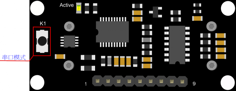
Button for RS232/TTL Choosing
The first basic step to communicate with the model is to choose the serial level_TTL(default) or RS232. We step forward over the last version3.2 which by jumper, now we could do it by pressing the only one button on the board for 1 second, after the light turn off from state-on, release the botton. Repower again, the indicator appears to flash like once long and once short -present TTL level output, once long and twice short flash presenting RS232 level.
 Do not connect the sensor to TTL MCU when the output mode is set to RS232, doing so will permanently damage the unit.
Test on Software
This feature is only available for Rev2 and after. If there are no jumpers, or no button on the back of the sensor, the sensor should be Rev1 and hence not supporting this feature.
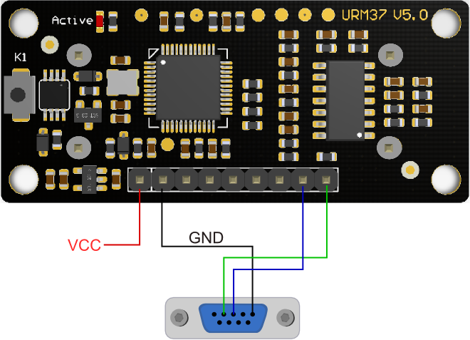
Power on the sensor, read the blink of the LED(active) to get the serial level(see above), wire according to the above picture. After this, you can use our "URMV3.2HelpMate" to test the module.
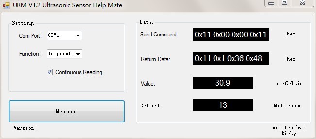
The usage of the software is very simple: ensure that there is no other software on the computer occupying the serial port, and then run Mate.exe, select the COM Port, and choose the parameter what you want to measure, and choose the "Continuous Reading ". Click "Measure" it will measure the temperature and the distance.
Other Setting address in EEPROM
Here, we are talking about the meaning of the data in EEPROM several addresses.(For more details, can be found in the Serial control protocol part)
| Address | Meaning |
| 0x00 | larger than set distance |
| 0x01 | less than set distance |
| 0x02 | measure mode(write 0xaa present automatically measure mode, other data except 0xaa present PWM Passive measurement mode ) |
| 0x03 | Serial level mode(TTL/RS232)(write 0x00 present TTL mode, 0x01 present RS232 mode, other data will be modified to 0x00) |
| 0x04 | automatically measure time span(minimum value: 70ms; maximum value: 255ms; default value: 100ms. Witting format is 8-bit 16 binary,and its unit is ms. e.g. Write 6E means 110ms) |
| 0x05 | measure sensitivity(the range of writing data is 0x0a-0xc8(equivalent to decimal 10-200), the smaller the value, the higher the sensivity. The default value is 0x0a, and the sensitivity is the highest.) |
The factory default settings
- Serial TTL level
- Measure mode: PWM trigger
- Comparison of distance : 0
- Automatically measure interval time:25ms
- Internal EEPROM Data are all 0x00
- the EEPROM address are unavailable: 0x00~0x04, please do not try to modify the data.
Three Measure Modes
PWM trigger mode
PWM Output in Trigger Mode
In trigger mode, pin COMP/TRIG produces a trigger pulse signal of low level,starting distance measurement operation once. At the same time, this low level pulse width represents the parameter for controlling the angle of the servo's rotation. 180 degree split into 46 angle controlling parameters, which means each parameter is equal to 4 degree. The parameter ranges from 0 to 45 and every 50US pulses represent a angle controlling parameter. When send out the trigger pulse, the MOTO pin of the module will produce servo controlling pulse to alter the rotating degree of the servo. And then the detected distance will be output in the form of low level pulse via PWM from the ECHO pin. Every 50US pulses represent 1 centimeter. In this way, we can read the distance. The measurement is invalid if it returns a pulse of 50000US.
Upload the code below to your arduino board, wire the devices together, then you can realize the distance measurement.
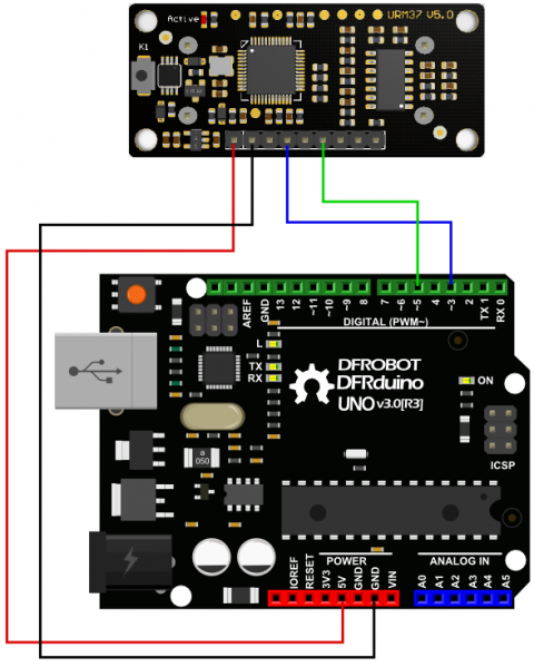
Demo code
// # Editor     : roker
// # Date       : 05.03.2018

// # Product name: URM V5.0 ultrasonic sensor
// # Product SKU : SEN0001
// # Version     : 1.0

// # Description:
// # The Sketch for scanning 180 degree area 2-800cm detecting range
// # The sketch for using the URM37 PWM trigger pin mode from DFRobot
// #   and writes the values to the serialport
// # Connection:
// #       Vcc (Arduino)    -> Pin 1 VCC (URM V5.0)
// #       GND (Arduino)    -> Pin 2 GND (URM V5.0)
// #       Pin 3 (Arduino)  -> Pin 4 ECHO (URM V5.0)
// #       Pin 5 (Arduino)  -> Pin 6 COMP/TRIG (URM V5.0)

// # Working Mode: PWM trigger pin  mode.

int URECHO = 3;         // PWM Output 0-50000US,Every 50US represent 1cm
int URTRIG = 5;         // trigger pin

unsigned int DistanceMeasured = 0;

void setup()
{
  //Serial initialization
  Serial.begin(9600);                        // Sets the baud rate to 9600
  pinMode(URTRIG, OUTPUT);                   // A low pull on pin COMP/TRIG
  digitalWrite(URTRIG, HIGH);                // Set to HIGH
  pinMode(URECHO, INPUT);                    // Sending Enable PWM mode command
  delay(500);
  Serial.println("Init the sensor");

}
void loop()
{
  Serial.print("Distance=");
  digitalWrite(URTRIG, LOW);
  digitalWrite(URTRIG, HIGH);

  unsigned long LowLevelTime = pulseIn(URECHO, LOW) ;
  if (LowLevelTime >= 50000)              // the reading is invalid.
  {
    Serial.println("Invalid");
  }
  else
  {
    DistanceMeasured = LowLevelTime / 50;  // every 50us low level stands for 1cm
    Serial.print(DistanceMeasured);
    Serial.println("cm");
  }

  delay(200);
}
Result
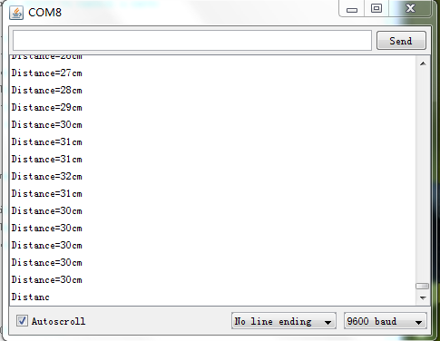
Arduino will send the distance to master computer through serial port. The baud rate should be set to 9600.
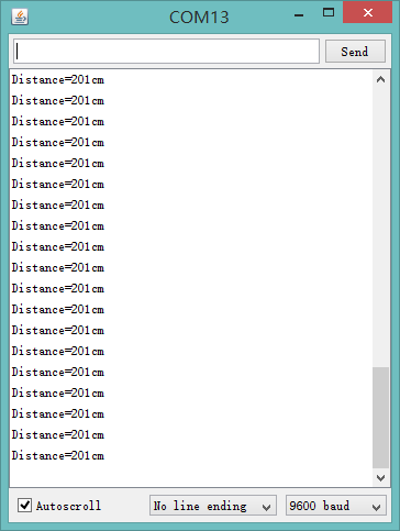
Analog Voltage Output in Trigger Mode
Once we are able to implement the most basic measurements, we can use more of the features on our module, such as the analog voltage output function mentioned above. The output voltage is proportional to the measured distance with the proportion of 4.125mV / cm. when exceeded the measurement range, the output voltage is 3.3V at full voltage. By reversing the code”#define Measure 1 ” to “#define Measure 0”, we can read the distance by analog voltage.
Upload the demo code to Arduino, and connect the ultrasonic sensor with Arduino as the way shown below.
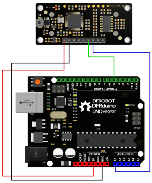
Demo Code
// # Editor     : roker
// # Date       : 05.03.2018

// # Product name: URM V5.0 ultrasonic sensor
// # Product SKU : SEN0001
// # Version     : 1.0

// # Description:
// # The Sketch for scanning 180 degree area 2-800cm detecting range
// # The sketch for using the URM37 PWM trigger pin mode from DFRobot
// #   and writes the values to the serialport
// # Connection:
// #       Vcc (Arduino)    -> Pin 1 VCC (URM V5.0)
// #       GND (Arduino)    -> Pin 2 GND (URM V5.0)
// #       Pin 5 (Arduino)  -> Pin 6 COMP/TRIG (URM V5.0)
// #       Pin A0 (Arduino) -> Pin 7 DAC (URM V5.0)

int URTRIG = 5;         // trigger pin
int sensorPin = A0;     // select the input pin for the potentiometer
int sensorValue = 0;    // variable to store the value coming from the sensor

unsigned int DistanceMeasured = 0;

void setup()
{
  //Serial initialization
  Serial.begin(9600);                        // Sets the baud rate to 9600
  pinMode(URTRIG, OUTPUT);                   // A low pull on pin COMP/TRIG
  digitalWrite(URTRIG, HIGH);                // Set to HIGH
  delay(500);
  Serial.println("Init the sensor");

}
void loop()
{
  Serial.print("Distance=");
  digitalWrite(URTRIG, LOW);
  digitalWrite(URTRIG, HIGH);
  delay(200);
  sensorValue = analogRead(sensorPin);

  sensorValue = sensorValue * 1.1; //  (sensorValue * 5000 / 1024 ) / 4.125 = sensorValue * 1.1 , calculate the voltage value ADC collected and divide it by 4.125mV /cm.
  Serial.print(sensorValue);
  Serial.println("cm");

}
Note: the error of the distance got by calculating output analog voltage is bigger than that of the distance by other ways.
Auto Measure Mode
By means of the computer software or MCU Module, write 0xAA to 0x02 address to switch to automatic measurement mode. Writting a 8-bit 16 binary data to 0x04 address to reverse the measure time interval.
This module measures distance automatically every 25 ms (Settable) , then compare the data with the set value, if equal to or less than the set value, COMP/TRIG pin output low. In addition, in every measure, the PWM Terminal will read the distance as a low level pulse, 50uS represents 1 cm.
Tips: if you have set the Compare value, you could use this module as a Ultrasonic Switch.
Download the sample code to the Arduino board, then wire as shown modules and Arduino connected on ultrasonic distance measurement can be achieved.
Note:download first before connect the Arduino TX/RX, otherwise it will fail.
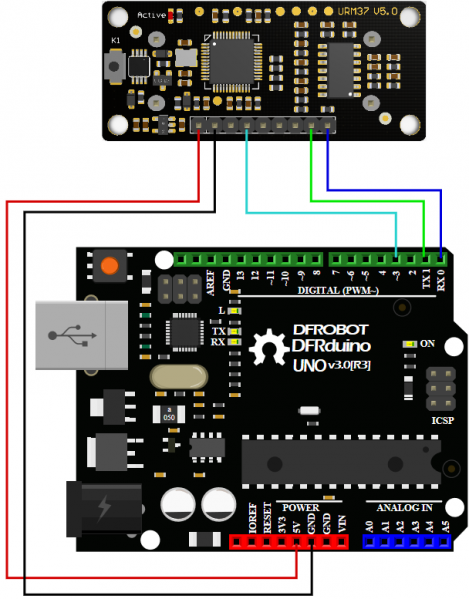
Demo Code
// # Editor     : roker
// # Date       : 05.03.2018

// # Product name: URM V5.0 ultrasonic sensor
// # Product SKU : SEN0001
// # Version     : 1.0

// # Description:
// # The sketch for using the URM37 autonomous  mode from DFRobot
// #   and writes the values to the serialport


// # Connection:
// #       Vcc (Arduino)      -> Pin 1 VCC (URM V5.0)
// #       GND (Arduino)      -> Pin 2 GND (URM V5.0)
// #       Pin 3 (Arduino)    -> Pin 4 ECHO (URM V5.0)
// #       Pin TX1 (Arduino)  -> Pin 8 RXD (URM V5.0)
// #       Pin RX0 (Arduino)  -> Pin 9 TXD (URM V5.0)
// # Working Mode:  Automatic measurement model.

int URECHO = 3; // PWM Output 0-50000US,Every 50US represent 1cm

unsigned int Distance = 0;
uint8_t AutomaticModelCmd[4] = {0x44, 0x02, 0xaa, 0xf0}; // distance measure command

void setup()
{
  Serial.begin(9600);           // Serial initialization
  delay(5000);                   // wait for sensor setup
  AutomaticModelSetup();        //Automatic measurement model set
}

void loop()
{
  AutomaticMeasurement();
  delay(100);
}


void AutomaticModelSetup(void)
{
  pinMode(URECHO, INPUT);
  for (int i = 0; i < 4; i++)
  {
    Serial.write(AutomaticModelCmd[i]);// Sending Automatic measurement model command
  }
}


void AutomaticMeasurement(void)
{
  unsigned long DistanceMeasured = pulseIn(URECHO, LOW);
  if (DistanceMeasured >= 50000) // the reading is invalid.
  {
    Serial.print("Invalid");
  }
  else
  {
    Distance = DistanceMeasured / 50;       // every 50us low level stands for 1cm
    Serial.print("Distance=");
    Serial.print(Distance);
    Serial.println("cm");
  }
}
Result
Arduino sends the distance information to the computer through serial port.
Serial Passive Mode
In this mode, actually, as long as you wire the module TX & RX with the MCU, just as we did in the test on software,you are using this mode.By serial, you have all authority to access to the sensor such as: ultrasonic distance measurement, temperature measurement, the distance changes, automatic measurement intervals set, serial port set(RS232 or TTL, reboot to take effect).
e.g.
- Read the temperature data command: 0x11 0x00 0x00 0x11
- Read the distance data command: 0x22 0x00 0x00 0x22
- Read EEPROM data command: 0x33 0x00 0x00 0x33
- Write EEPROM data command: 0x44 0x02 0x00 0x46
Download the code below to your uno board(if you use the leonardo,please modify the code for the serial problem, help on arduino.cc ), then wire the TX/RX,5V,GND.Follow test on software.Here,we use the sensor to read the tempreture.
Demo Code
// # Editor     : roker
// # Date       : 05.03.2018

// # Product name: URM V5.0 ultrasonic sensor
// # Product SKU : SEN0001
// # Version     : 1.0

// # Description:
// # The sketch for using the URM37 Serial  mode from DFRobot
// #   and writes the values to the serialport

// # Connection:
// #       Vcc (Arduino)      -> Pin 1 VCC (URM V5.0)
// #       GND (Arduino)      -> Pin 2 GND (URM V5.0)
// #       Pin TX1 (Arduino)  -> Pin 8 RXD (URM V5.0)
// #       Pin RX0 (Arduino)  -> Pin 9 TXD (URM V5.0)
// # Working Mode: Serial  Mode.

uint8_t EnTempCmd[4] = {0x11, 0x00, 0x00, 0x11}; // temperature measure command
uint8_t TempData[4];
unsigned int TempValue = 0;
void setup()
{
  Serial.begin(9600);
  delay(100);
  Serial.println("Init the sensor");
}
void loop()
{
  SerialCmd();
  delay(200);
}
void SerialCmd()
{
  int i;
  for (i = 0; i < 4; i++) {
    Serial.write(EnTempCmd[i]);
  }
  while (Serial.available() > 0)  // if received data
  {
    for (i = 0; i < 4; i++) {
      TempData[i] = Serial.read();
    }
    TempValue = TempData[1] << 8;
    TempValue = TempValue + TempData[2];
    Serial.print("temperature : ");
    Serial.print(TempValue, DEC);
    Serial.println(" oC");
  }
}
Result
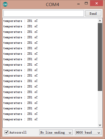
This temperature was magnified 10 times, in the test, actual tempreture is 28.1 degrees Celsius.
Servo Rotation Reference Table
| DEC | 0 | 1 | 2 | 3 | 4 | 5 | 6 | 7 | 8 | 9 | 10 | 11 | 12 | 13 | 14 | 15 |
| HEX | 0 | 01 | 02 | 03 | 04 | 05 | 06 | 07 | 08 | 09 | 0A | 0B | 0C | 0D | 0E | 0F |
| Degree | 0 | 6 | 12 | 18 | 24 | 29 | 35 | 41 | 47 | 53 | 59 | 65 | 70 | 76 | 82 | 88 |
| DEC | 16 | 17 | 18 | 19 | 20 | 21 | 22 | 23 | 24 | 25 | 26 | 27 | 28 | 29 | 30 | 31 |
| HEX | 10 | 11 | 12 | 13 | 14 | 15 | 16 | 17 | 18 | 19 | 1A | 1B | 1C | 1D | 1E | 1F |
| Degree | 94 | 100 | 106 | 112 | 117 | 123 | 129 | 135 | 141 | 147 | 153 | 159 | 164 | 170 | 176 | 182 |
| DEC | 32 | 33 | 34 | 35 | 36 | 37 | 38 | 39 | 40 | 41 | 42 | 43 | 44 | 45 | 46 | |
| HEX | 20 | 21 | 22 | 23 | 24 | 25 | 26 | 27 | 28 | 29 | 2A | 2B | 2C | 2D | 2E | |
| Degree | 188 | 194 | 200 | 206 | 211 | 217 | 223 | 229 | 235 | 241 | 247 | 252 | 258 | 264 | 270 |
Arduino Sketch
NOTE: Please put the sensor jumpers to TTL mode. See above for a picture indicating TTL mode.
``` cpp

// # Editor    : Jiang from DFRobot
// # Data      : 24.07.2012

// # Product name:ultrasonic scanner Kit
// # Product SKU:SEN0001
// # Version :  0.2

// # Description:
// # The Sketch for scanning 180 degree area 4-500cm detecting range

// # Connection:
// #       Pin 1 VCC (URM V3.2) -> VCC (Arduino)
// #       Pin 2 GND (URM V3.2) -> GND (Arduino)
// #       Pin 4 PWM (URM V3.2) -> Pin 3 (Arduino)
// #       Pin 6 COMP/TRIG (URM V3.2) -> Pin 5 (Arduino)
// # Pin mode: PWM
// # Working Mode: PWM passive control mode.
// # If it is your first time to use it,please make sure the two jumpers to the right hand
// # side of the device are set to TTL mode. You'll also find a secondary jumper on
// # the left hand side, you must break this connection or you may damage your device.

#include <Servo.h>                                  // Include Servo library
Servo myservo;                                      // create servo object to control a servo

int pos=0;                                          // variable to store the servo position
int URPWM=3;                                        // PWM Output 0-50000us,every 50us represent 1cm
int URTRIG=5;                                       // PWM trigger pin
boolean up=true;                                    // create a boolean variable
unsigned long time;                                 // create a time variable
unsigned long urmTimer = 0;                          // timer for managing the sensor reading flash rate

unsigned int Distance=0;
uint8_t EnPwmCmd[4]={0x44,0x22,0xbb,0x01};          // distance measure command

void setup(){                                      // Serial initialization
  Serial.begin(9600);                              // Sets the baud rate to 9600
  myservo.attach(9);                                // Pin 9 to control servo
  PWM_Mode_Setup();
}

void loop(){
   if(millis()-time>=20){                           // interval 0.02 seconds
     time=millis();                                 // get the current time of programme
     if(up){                                        // judge the condition
      if(pos>=0 && pos<=179){
        pos=pos 1;                                  // in steps of 1 degree
        myservo.write(pos);                         // tell servo to go to position in variable 'pos'
      }
      if(pos>179)  up= false;                       // assign the variable again
    }
     else {
      if(pos>=1 && pos<=180){
        pos=pos-1;
        myservo.write(pos);
      }
      if(pos<1)  up=true;
    }
   }

   if(millis()-urmTimer>50){
     urmTimer=millis();
     PWM_Mode();
   }
 }

 void PWM_Mode_Setup(){
  pinMode(URTRIG,OUTPUT);                            // A low pull on pin COMP/TRIG
  digitalWrite(URTRIG,HIGH);                         // Set to HIGH

  pinMode(URPWM, INPUT);                             // Sending Enable PWM mode command

  for(int i=0;i<4;i  ){
      Serial.write(EnPwmCmd[i]);
   }
}

void PWM_Mode(){                                     // a low pull on pin COMP/TRIG  triggering a sensor reading
    digitalWrite(URTRIG, LOW);
    digitalWrite(URTRIG, HIGH);                      // reading Pin PWM will output pulses

    unsigned long DistanceMeasured=pulseIn(URPWM,LOW);

    if(DistanceMeasured==50000){                     // the reading is invalid.
      Serial.print("Invalid");
   }
    else{
      Distance=DistanceMeasured/50;                  // every 50us low level stands for 1cm
   }
  Serial.print("Distance=");
  Serial.print(Distance);
  Serial.println("cm");
}
Protocol
Serial setting:Port rate: 9600; Parity: none; Stop bit: 1
Command: Control command consists of four bits, command data0 data1 sum. Sum=Low 8 bit of the sum of command data0 data1.
| Command Format | Function | Description |
|---|---|---|
| 0x11+NC+NC+Sum (Sample: 0x11 0x00 0x00 0x11) | Enable 16 bit temperature reading | Reading the temperature, the return data format will be: 0x11 High(temperature) Low(temperature) SUM; If the temperature is above 0, the first four bits of High will be all 0. If the temperature is below 0, the first four bits of High will be all 1; The last 4 bits of High together with the Low bits stands for 12bits temperature. The resolution is 0.1. When the reading is invalid, it returns 0x11 0xFF 0xFF SUM |
| 0x22+Degree+NC+SUM (Sample: 0x22 0x00 0x00 0x22 ) | Enable 16 bit distance reading | The degree in the command is used to control a servo motor to rotate corresponding degree; Degree: 0-46 stands for 0-270 degrees, for example, 3 stands for 18 degrees; Return data format will be: 0x22+High(distance)+Low(distance) SUM. When the reading is invalid, it returns 0x22 0xFF 0xFF SUM |
| 0x33+Add+NC+SUM | Enable internal EEPROM reading | Return data will be 0x33+Add+Data+SUM. |
| 0x44+Add+Data+SUM (Sample: 0x44 0x02 0xbb 0x01) Enable PWM mode | Enable internal EEPROM writing | Written data can only from 0-255. Address 0x00-0x02 is used to configure the mode. 0x00 – threshold distance (Low) 0x01 – threshold distance (High) 0x02 – Operation Mode (0xaa for autonomous mode) (0xbb for PWM passive control mode);The return data format will be: 0x44+Add+Data+SUM |
NOTE: NC stands for any data,SUM stands for sum, Add stands for address.
1. PWN_ON must be set to High to enable sensor.
Examples: Function to calculate the temperature:
IF(HightByte>=0xF0)
{
Temperature= ((HightByte-0xF0)*256-LowByte)/10
 }
Else
{
Temperature= ((HightByte)*256-LowByte)/10
}
The delineation of detection angles and sensitivity levels
The physical attributes of ultrasonic sensors inherently beget irregular detection zones. Consequently, the precise definition of the detection angle for ultrasonic ranging sensors poses a challenge. We conducted tests on various sample products using two distinct reference obstacles, and the respective reference detection zones for these targets are as illustrated in the diagrams below:
-
Diagram of the detection zone for a PVC pipe with a diameter of 7.5 cm
-
Diagram of the detection zone for a rectangular plane obstruction measuring 47 cm by 100 cm.
Trouble shooting
- If you have connected sensor to the Arduino, but unable to use it, please first check the current serial port-level mode, it may be in TTL level, while our module works in RS232 levels.
- The ultrasonic attenuation violently in the air (inversely proportional to the d²(distance)), besides, barrier surface reflection of the sound is affected by many factors (such as barrier shape, orientation and texture) the influence of ultrasonic distance measurement is therefore limited.
- The far testing distance is a wall, close test can be a pen. Analyte based on the use of the environment and quality of different measurement may result in inconsistent with the data provided.
- The mentioned servo above is a ordinary model on the market, can be rotated 180 degrees. If you use a special steering servo, it may draw the user's attention to control the timing in a different way.
- If you are experiencing technical issues, please ask on our forum or send us email, we will answer your questions as soon as possible.
For any questions, advice or cool ideas to share, please visit the DFRobot Forum.