Introduction
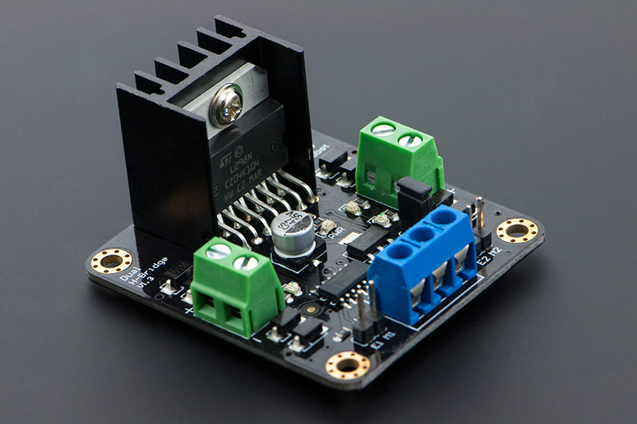
This is a 4.8-46V, 2A Dual Motor Controller which is the revised version of the DF-MDV1.0. Its performance has been improved greatly. It can bear larger current due to the increased haetsink dissipation. It is easy to control, using LGS's outstanding high-power motor driver chip, the L298N. This chip allows for direct drive of two bi-directional DC motors, and incorporates high-speed short diodes for protection. Drive current up to 2A per motor output. The driver uses a broad-brush design to reduce wire resistance.
**Note:**For the screws of the terminal block, in different batches, the screws may be slotted screws or Phillips screws.
Specifications
- The logic part of the input voltage: 6 ~ 12V
- Driven part of the input voltage Vs: 4.8 ~ 46V
- The logical part of the work current Iss: 36mA
- Drive part of the operating current Io: 2A
- Maximum power dissipation: 25W (T = 75 degree Celsius)
- Control signal input level:
- High level: 2.3V = Vin = Vss
- Low:-0.3V = Vin = 1.5V
- Operating temperature: -25 degree Celsius ~ +130 degree Celsius
- Drive Type: Dual high-power H-bridge driver
- Module Size: 47 mm × 53mm
- Module Weight: About 29g
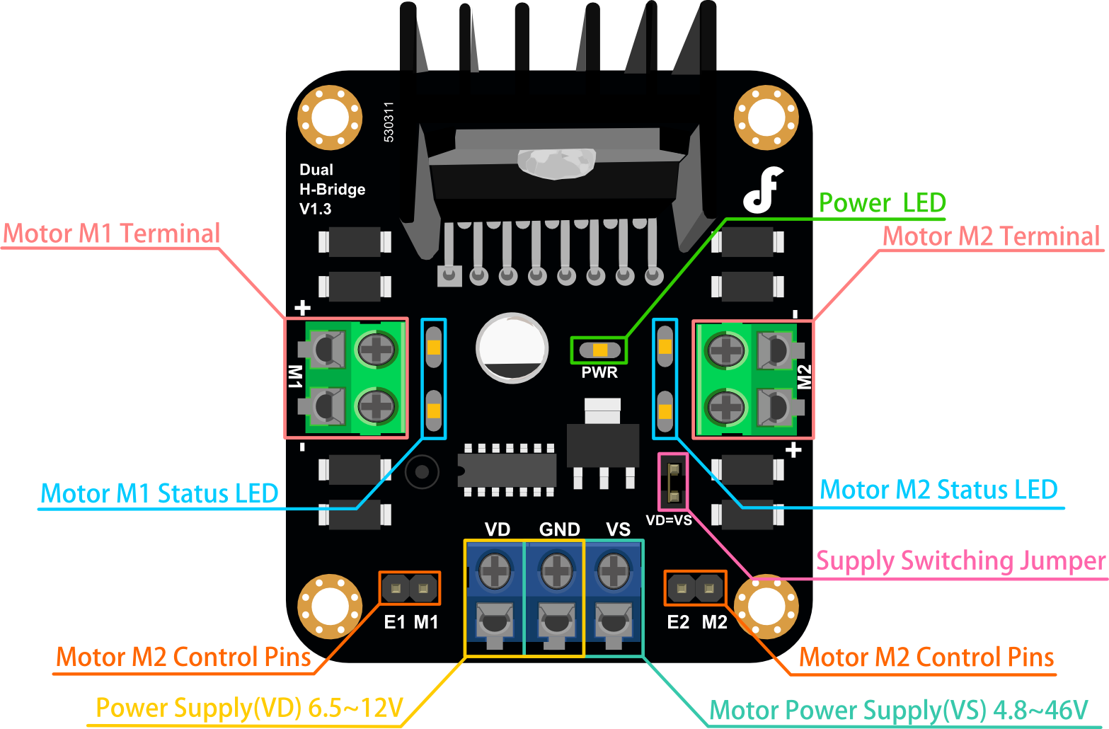
Board Overview

Detailed Descriptions
Motor Terminal
The terminals are used to connected to the motors, which labeled "+" and "-" representing motor polarity.
LED
- PWM: Power LED
- Motor Status LED: Motors work normally, thus the lED will light up.
Power

- VD: Power Supply 6.5V~12V;
- VS: Motor Power Supply 4.8~46V;
- GND: The common ground of Logic Power Supply and Motor Supply
Supply Switching Jumper

When jumper is shorted, logic power supply voltage is the same as the motor power supply.
If motor power supply is less than 12V,you can set jumper shorted.
If motor power supply is more than 12V, dont't short jumper!
Motor Control Pins
- E1,E2: Motor Enable Pin(PWM Control)
- M1,M2: Motor Signal Pin. Eg: M1 = 0,the motor rotates in forward direction. M1 = 1,the motor rotates in back direction.
| E | M | RUN |
|---|---|---|
| LOW | LOW/HIGH | STOP |
| HIGH | HIGH | Back Direction |
| HIGH | LOW | Forward direction |
| PWM | LOW/HIGH | Speed |
Note: LOW = 0; HIGH = 1; PWM = 0~255
Tutorial
This tutorial shows you how to use l298N motor drive shield to drive two DC motors.
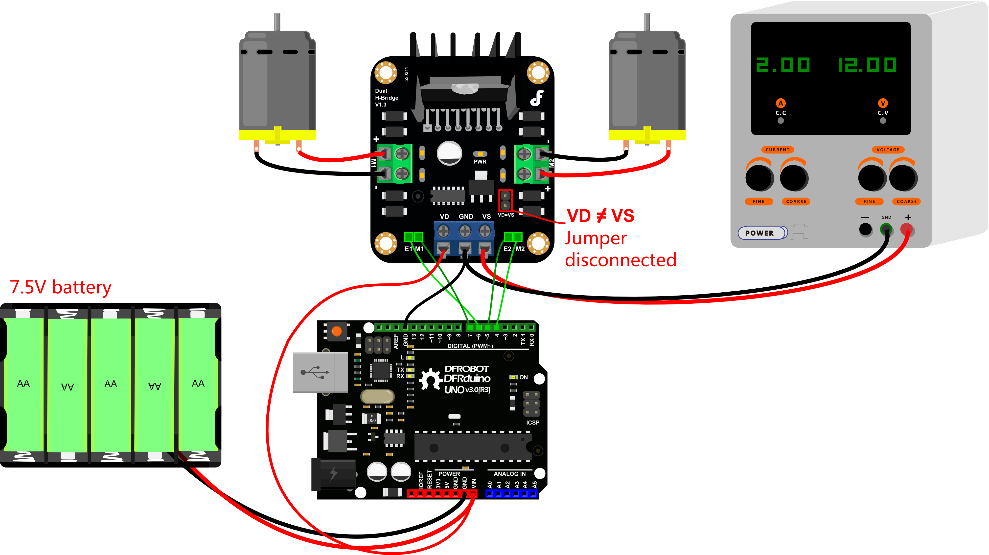
Connection Diagram

Sample Code
// # Editor     : Lauren from DFRobot
// # Date       : 17.02.2012

// # Product name: L298N motor driver module DF-MD v1.3
// # Product SKU : DRI0002
// # Version     : 1.0

// # Description:
// # The sketch for using the motor driver L298N
// # Run with the PWM mode

// # Connection:
// #        M1 pin  -> Digital pin 4
// #        E1 pin  -> Digital pin 5
// #        M2 pin  -> Digital pin 7
// #        E2 pin  -> Digital pin 6
// #        Motor Power Supply -> Centor blue screw connector(5.08mm 3p connector)
// #        Motor A  ->  Screw terminal close to E1 driver pin
// #        Motor B  ->  Screw terminal close to E2 driver pin
// #
// # Note: You should connect the GND pin from the DF-MD v1.3 to your MCU controller. They should share the GND pins.
// #

int E1 = 6;
int M1 = 7;
int E2 = 5;
int M2 = 4;

void setup()
{
    pinMode(M1, OUTPUT);
    pinMode(M2, OUTPUT);
}

void loop()
{
  int value;
  for(value = 0 ; value <= 255; value+=5)
  {
    digitalWrite(M1,HIGH);
    digitalWrite(M2,HIGH);
    analogWrite(E1, value);   //PWM Speed Control
    analogWrite(E2, value);   //PWM Speed Control
    delay(30);
  }
}
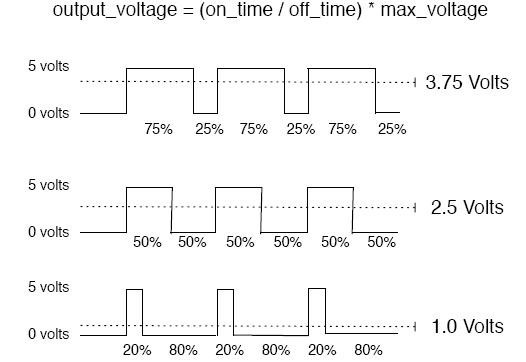
PWM Principle

FAQ
| Q&A | Some general Arduino Problems/FAQ/Tips |
|---|---|
| A | For any questions, advice or cool ideas to share, please visit the DFRobot Forum. |
