Introduction
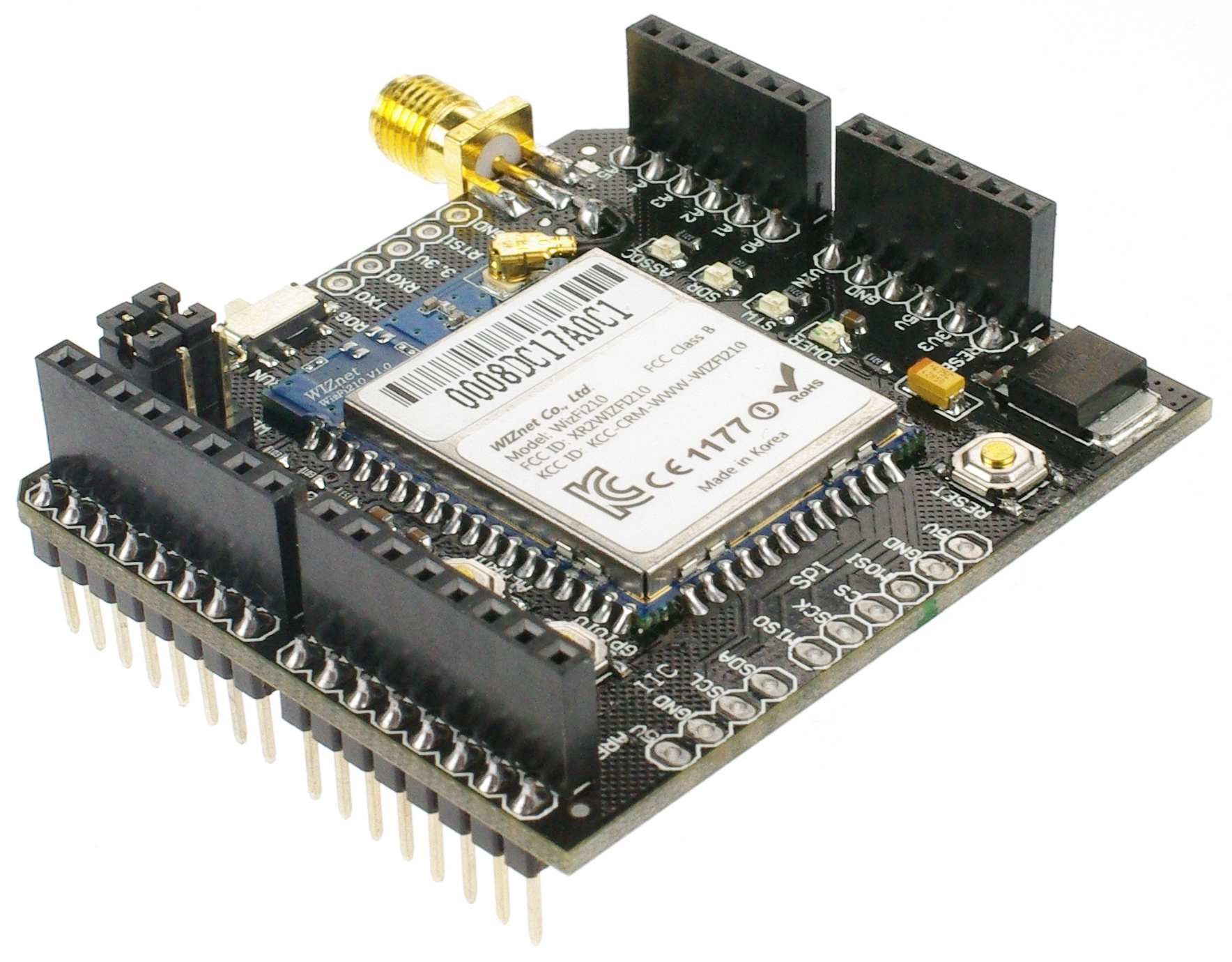
The shield uses WizFi210 which is a low power-consuming WIFI module which is applied with dynamic power management technology. When the WIFI module needs to be on but not work, it can be set to Standby mode a low power mode, and the module just needs to be woken up when it has to work. The WIFI wireless module is based on WizFi210. It provides the bridging from TTL serial port communication to IEEE802.11b/g/n wireless communication. So any device with TTL serial ports can easily be connected with this WIFI module and controlled and managed remotely through a wireless network. Different kinds of communication protocols and encryption algorithms are integrated with the module. The Arduino architecture enables you to easily integrate this module into any Arduino based project.
Features
- Bring WiFi connectivity via Serial Host Interface, compatiable with Arduino
- Quick Booting Time : under 20msec
- Ultra Low Power through Dynamic Power Management (34µA at the Standby mode)
- Operates with standard 802.11b/g/n access point at speed up to 11Mbps (802.11b)
- Security Protocol : WEP, WPA/WPA2-PSK, Enterprise, EAP-FAST, EAP-TLS, EAP-TTLS, PEAP
- Operation Temperature : -40℃ ~ 85℃
- Compact Size : 32 x 23.5 x 2.9 (mm)
- CE, FCC, KCC Certified
- Supports the module with chip antenna
- 802.11b/g/n
Specifications
- Wifi Chip: WizFi210
- Radio Protocol: IEEE 802.11b/g/n Compatible
- Supported Data Rates: 11, 5.5, 2, 1 Mbps (IEEE 802.11b)
- Modulation: DSSS and CCK
- RF Operating Frequency: 2.4 - 2.497 GHz
- Antenna Options: Chip antenna and U.FL connector for external antenna
- Networking Protocols: UDP, TCP/IP (IPv4), DHCP, ARP, DNS, HTTP/HTTPS Client and Server(*)
- Power Consumption(Typical): Standby = 34.0 µA Receive = 125.0 mA Transmit = 135.0 mA
- RF Output Power (Typical): 8dBm ± 1dBm
- Security Protocols: WEP, WPA/WPA2–PSK, Enterprise, EAP-FAST, EAP-TLS, EAP-TTLS, PEAP
- I/O Interface: UART, SPI(*), I2C(*), WAKE, ALARM, GPIOs
- Power Source: 3.3V
- Dimensions(except Antenna): 59 x 54 mm
Documents
Shield Pin Allocation
| Pin | Function |
|---|---|
| Digital 0 | RX |
| Digital 1 | TX |
Wifi Shield
Initial Setup
The wifi shield is actually quite straight away. You can take it as a serial communication device. For arduino code, you only need the following code:
Serial.print()
However, before making it work, you need to configure the wifi as any standard wifi device.
jumper configurations
The Wifi shield has 2 sets of jumpers and one switch.
| Pin | Function |
|---|---|
| USB | wifi configuration (AT mode) |
| WIFI | Arduino to wifi communication |
| NONE | shield disable. Allows Arduino programming |
Jumper settings
| setting | Function |
|---|---|
| RUN | wifi configuration (AT mode) |
| PROG | Arduino to wifi communication |
switch settings
AT Mode Configuration
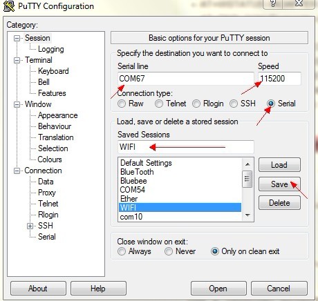
To enter AT Mode set the jumpers to "USB" and the switch to "RUN" use a terminal program like PuTTy and connect to the Arduino's com port at 115200 Bps.
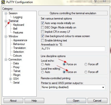
Configuring PuTTy
Before you open a PuTTy session you should configure PuTTy to display your input and the module's output.
Step 1:

Step 2:

Please change the com port value to your Arduino's com port. You can check this in the Arduino's IDE.
AT Commands
The following AT commands are a quick review of the essentials needed to get your Wifi Shield connected to your network with a UDP server running on port 4000. This is not meant to be an all encompassing tutorial. If you would like to make a more complex setup please refer to the WizFi datasheet provided in the documents section of this wiki for a complete list of AT commands and their description.
| Command | Function |
|---|---|
| AT | ENTER AT MODE |
| AT+WD | DISASSOCIATE FROM PREVIOUS CONNECTION |
| AT+WWPA=AP_PASSWORD | SET WIRELESS PASSWORD. FOR MORE SECURITY OPTIONS PLEASE SEE Pg28 OF WizFi DATASHEET V101 |
| AT+NDHCP=1 | ENABLE DHCP SETTINGS. AUTO-ASSIGN IP ADDRESS. YOU MIGHT WANT TO DISABLE THIS OPTION "0" AND SET YOUR OWN IP ADDRESS. SEE WIZFI DATASHEET FOR MORE DETIALS. |
| AT+WA=YOURSSID | DEFINE ROUTER'S "SSID" |
| AT+NSTAT=? | CURRENT WIRELESS AND NETWORK CONFIG. NOTE: Write down the reported IP address. you will need it later |
| AT+WSTATUS | ADAPTER REPORTS THE CURRENT NETWORK CONFIG TO SERIAL HOST |
| AT+DNSLOOKUP=google.com | TEST YOUR CONNECTION TO THE INTERNET. IF SUCCSESSFUL IT WILL RETURN GOOGLE'S IP ADDRESS |
| AT+NSTCP=5000 | SET TCP SERVER AT PORT 5000 |
| AT+NSUDP=4000 | SET UDP SERVER AT PORT 4000 |
| AT+CID=? | RETURNS THE CURRENT CID CONFIGURATION |
| ATC1 | SET TO AUTOCONNECT AT RESTART |
| AT&W0 | SAVE SETTINGS TO PROFILE "0" |
| ATA | CONNECT |
Test Code
Once you have verified that your Shield is connected to the internet you can upload this sketch to your Arduino by simply removing the 2 jumpers, then replacing them once the sketch has been uploaded. There is no need to change the settings for this, so just replace them back on "USB" mode.
You can test WiFi communication with this shield by removing the USB cable and providing external power. It is recommended that you provide 7.5Vdc and 1A to ensure the Wifi Radio has enough power.
You should now be able to connect to your shield's IP address and the specified UDP port using PuTTy.
Pressing 1 and 0 should turn LED 13 on and off, while reporting back to you on the PuTTY screen.
void setup() {
  pinMode(13, OUTPUT);
  Serial.begin(115200);
  delay(100);
  Serial.println("Press any key to continue");
  while(Serial.available()==0);
  Serial.println("  Lets test the DFRobot WiFi Shield");
  Serial.println("Press 1 to light the LED, and 0 to turn it off");
  Serial.println("Entery: ");
  digitalWrite(13, HIGH);
}

void loop() {

  if (Serial.available()){

    char input = Serial.read();
    switch (input){
    case '1':
      digitalWrite(13, HIGH);
      Serial.println("ON");
      delay(500);
      break;
    case '0':
      digitalWrite(13, LOW);
      Serial.println("OFF");
      delay(500);
      break;
    }
  }
}
Version change log
V2.2 Improvements:
- For the Buttons:
- Improve the reset button to reset the Arduino and wifi module at the same time
- GPIO29 disconnect the wifi network connection
- For the Swtiches:
- Run/Prog Communicate with the Wifi / Disconnect the TTL pins from Wifi for programming Arduino
- USB/Arduino Drive the wifi directly via USB communication / Drive the wifi module via Arduino TTL