Introduction
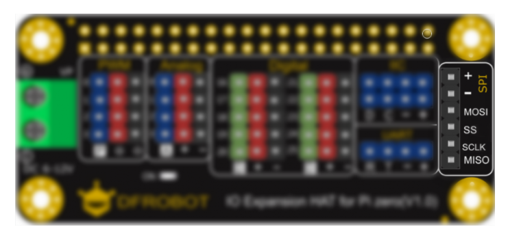
This DFRobot IO Expansion HAT provides Digital, Analog, I2C, PWM, UART and SPI port to meet all your needs. It is pretty small and perfectly suitable for Raspberry Pi Zero/Zero W.
The board leads out the I/O ports on Raspberry Pi including IIC, UART, SPI and digital, among which the digital ports are led out via the GPIO16~GPIO25(BCM) of Raspberry Pi, so these ports can be directly used. Besides, the PWM and Analog ports are led out through the on-board MCU STM32 that can communicate with Raspberry Pi via IIC. So combing with our related libraries, users are able to conveniently use Raspberry Pi to control PWM output or read ADC input.
Specification
- Power Supply: 5V
- External Power Supply (Servo): 6-12V
- Device Address: 0x10
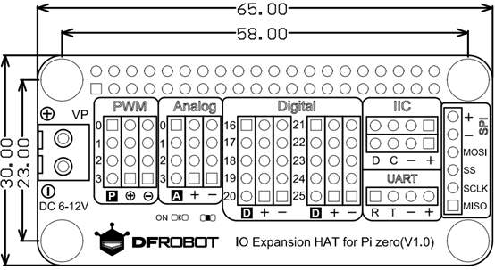
- Dimension: 65x30mm/2.56x1.18”
Board Overview


| Silkscreen | Label | Function |
|---|---|---|
| + | + | 3.3 Power Positive |
| - | - | Negative |
| ⊕ | ⊕ | External Power Positive |
| ㊀ | ㊀ | External Power Negative |
| Digital | 16-25 | Raspberry Pi (GPIO16-GPIO25) |
| PWM | 0-3 | PWM Signal Output P0~3 |
| Analog | 0-3 | Analog Signal Input P0~3 |
| IIC | C | IIC Clock line |
| D | IIC Data Line | |
| UART | T | UART Transmit |
| R | UART Receive | |
| SPI | MISO | SPI Data Output Line |
| SS | SPI Enable Pin | |
| SCLK | SPI Clock Line | |
| MOSI | SPI Data Input Line |
PWM
The PWM signal of this expansion board is generated by the on-board STM32. PWM0~PWM3 are output via multiple channels of one timer with same frequency. The duty ratio can be set by users. PWM4 adopts another timers to output PWM. The PWM can be powered by Raspberry Pi(5V) or external power(6-12V).

 Note:
Note:
- When the VP port is not power by external power, the voltage of PWM ⊕ is 5V.
- When the VP port is powered by external power, the voltage of PWM ⊕ is equal to that of the VP external power (6-12V).
Analog
The IO expansion board comes with an on-board MCU STM32 that provides 12 bit ADC. The voltage of analog sensor will be input into the 12-bit ADC sent to Raspberry Pi via IIC when the analog data is converted into digital data, by which to allow Raspberry Pi to read values of analog sensor.

Digital
The board leads out 10 GPIO (BCM encode) ports of Raspberry Pi: GPIO16, GPIO17, GPIO18, GPIO19, GPIO20, GPIO21, GPIO22, GPIO23, GPIO24, GPIO25.

IIC
There are two IIC ports on the board, and they are led out via Raspberry Pi's IIC. Connect the two ports to GPIO2(SDA.1)and GPIO3(SCL.1) of Raspberry Pi.

UART
The UART ports on the expansion board are led out through Pi's GPIO14(TXD)and GPIO15(RXD). Use UART port to communicate with Arduino, Esp8266 and so on.

SPI
Connect the SPI ports on the board to GPIO12(MOSI)and GPIO13(MISO).

Tutorial
Connection
Plug the IO expansion board into Raspberry Pi.
Download the Driver library
To use the analog and PWM ports in the board, download the driver library first. Press Ctrl+Alt+T to open the terminal, input the following command and hit Enter.
git clone https://github.com/DFRobot/DFRobot_RaspberryPi_Expansion_Board.git
Download the library and unzip the file. Input the following command into the terminal:
tar -xvzf DFRobot_RaspberryPi_Expansion_Board
Enter the directory of the uncompressed files:
cd DFRobot_RaspberryPi_Expansion_Board/raspberry/
Extended Ports Usage
- PWM: connect a servo to PWM P0. Create a file via the command of nano:
sudo nano servoTest.py
Add the following content:
# -*- coding:utf-8 -*-
# servoTest.py

import time

from DFRobot_RaspberryPi_Expansion_Board import DFRobot_Expansion_Board_IIC as Board
from DFRobot_RaspberryPi_Expansion_Board import DFRobot_Expansion_Board_Servo as Servo

board = Board(1, 0x10)  # Select i2c bus 1, set address to 0x10
servo = Servo(board)

if __name__ == "__main__":
  # Board begin and check the board's status
  while board.begin() != board.STA_OK:
    print("Error")
    time.sleep(1)
  print("Board begin success.")

  servo.begin()         # servo control begin

  while True:
    print("part of servos move to 0°")
    servo.move(0, 0) # PWM0
    '''
    servo.move(1, 0) # PWM1
    servo.move(2, 0) # PWM2
    servo.move(3, 0) # PWM3
    '''

    print("part of servos move to 180°")
    servo.move(0, 0) # PWM0
    '''
    servo.move(1, 0) # PWM1
    servo.move(2, 0) # PWM2
    servo.move(3, 0) # PWM3
    '''

    print("All servos move between 0°~180°")
    for i in range(0, 181):
      servo.move(board.ALL, i)
      time.sleep(0.008)
    time.sleep(0.002)
    for i in range(0, 181):
      i = 181 - i
      servo.move(board.ALL, i)
      time.sleep(0.008)
    time.sleep(0.002)
In the function servo.move() of the example, the first parameter is the PWM pin of the expansion board, the second one is rotation degree. The PWM selection list is shown below:
| PWM Pin of IO expansion board | Value of the first parameter |
|---|---|
| 0 | 0 |
| 1 | 1 |
| 2 | 2 |
| 3 | 3 |
| All Pins | board.ALL |
Press Ctrl+X, and then press Y to save and exit nano editor.
Input command sudo raspi-config to open the IIC interface.
Input command python servoTest.py to run file servoTest.py.
- Analog
Sample Code:
# -*- coding:utf-8 -*-
# analogTest.py

import time
from DFRobot_RaspberryPi_Expansion_Board import DFRobot_Expansion_Board_IIC as Board

board = Board(1, 0x10)  # Select i2c bus 1, set address to 0x10

if __name__ == "__main__":
  while board.begin() != board.STA_OK:  # Board begin and check the board's status
    print("Board begin faild.")
    time.sleep(1)
  print("Board begin success.")

  board.set_adc_enable()

  while True:
    print("Read part of channels.")
    val0 = board.get_adc_value(board.A0) # channel A0 is readed
    '''
    val1 = board.get_adc_value(board.A1) # channel A1 is readed
    val2 = board.get_adc_value(board.A2) # channel A2 is readed
    val3 = board.get_adc_value(board.A3) # channel A3 is readed
    '''

    print("channel:A0, value:%d" %val0)
    '''
    print("channel:A1, value:%d" %val1)
    print("channel:A2, value:%d" %val2)
    print("channel:A3, value:%d" %val3)
    '''
    print("")
    time.sleep(1)
The function board.get_adc_value() in the example is used to get the value of analog port, the pin selection list is shown below:
| Analog Pin of IO expansion board | Value of the parameter |
|---|---|
| 0 | 0 |
| 1 | 1 |
| 2 | 2 |
| 3 | 3 |
| All Pins | board.ALL |
- Digital: the usage of the digital ports are same with the ways to use GPIO ports of Raspberry Pi. Download the RPi.GPIO first. Input the command on Raspberry Terminal:
sudo apt-get install rpi.gpio
Input the following command to check is the RPi.GPIO library is installed successfully:
gpio.readall
If all pins are displayed on the terminal, the library installation succeeds.
Take GPIO16 as an example. Connect a LED on P27 of the expansion board.
Input the following sample code into nano editor, input python to run the program:
# -*- coding:utf-8 -*-
# digitalTest.py

import RPi.GPIO as GPIO
import time

blinkPin = 16

GPIO.setmode(GPIO.BCM)

GPIO.setup(blinkPin, GPIO.OUT)  # Set GPIO16 is OUTPUT

for i in range(0, 10):
  GPIO.output(blinkPin, 1)
  time.sleep(1)
  GPIO.output(blinkPin, 0)
  time.sleep(1)
GPIO.cleanup()
- IIC: for using IIC interface, input the command to enable the Raspberry Pi IIC first:
sudo raspi-config
Select [Interfacing Options]-[I2C]-[Yes]-[OK]-[Finish]. Restart the Raspberry Pi when completed these steps.
The usage of IIC ports on the expansion board is same with that of raspberry Pi, so we will skip here.
-
UART: The usage of UART ports on the expansion board is same with that of raspberry Pi, so we will skip here.
-
SPI: for using SPI interface, input the command to enable the Raspberry Pi IIC first:
sudo raspi-config
Select [Interfacing Options]-[I2C]-[Yes]-[OK]-[Finish].Restart the Raspberry Pi when completed these steps.
The usage of SPI ports on the expansion board is same with that of raspberry Pi, so we will skip here.
Product Dimension

Compatility Test
| MCU | Pass | Fail | Untest | Remark |
|---|---|---|---|---|
| Raspberry Pi 3B | √ | |||
| Raspberry Pi 3B+ | √ | |||
| Raspberry Pi Zero W | √ | |||
| Raspberry Pi 2B+ | √ | |||
| Raspberry Pi Zero | √ | |||
| Raspberry Pi 4B | √ |
FAQ
For any questions, advice or cool ideas to share, please visit the DFRobot Forum
