Home > Sensors & Modules > communication > GSM/GPRS/GPS
Introduction
With popularization of the concept of the Internet of things (IoT), more and more people want to know and make their own IoT device. The common WiFi cannot satisfy the mobile application scenarios, while the emerging NB-IoT network has a limited coverage area, so the most popular 2G network becomes one of the best choices at present.
DFRobot has updated the former GSM/GPRS expansion board, using the same series SIM800C GSM/GPRS chip as Mobike, in order to provide stable and reliable IoT links. A user may send AT instruction through UART communication interface, so as to make a call, send a short message and realize GPRS remote data acquisition, etc.
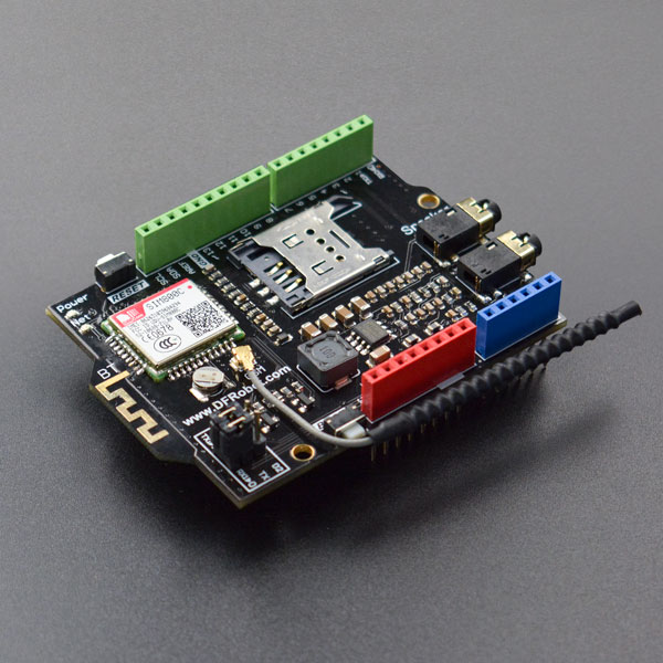
SIM800C GPRS/GSM expansion board is encapsulated by Arduino standard, and can be externally connected with Arduino UNO, Leonardo and other controllers. The expansion board is externally expanded with TX&RX interface by jumper. Communication can be connected by soft serial port for convenient development. The built-in Bluetooth 3.0 wireless communication function may cooperate with mobile phone to realize point-to-point communication, and see SIM800C User Manual for more advanced features.
 |
Caution: Since GSM is impulse type transmitting power, and the average current is very low, but the instantaneous current can reach more than 1.5A, so the external power supply is used in the use of GSM expansion board. USB port can only provide 5V@500mA, which cannot meet output of instantaneous power supply. |
Specification
- Power supply
: DC 7-23V - Quadruplex 850/900/1800/1900MHz
- GPRS multi-slot class 12/10
- GPRS mobile station class B
- GSM 2/2+standard
- Class 4 (2 W @ 850/900 MHz)
- Class 1 (1 W @ 1800/1900MHz)
- Control by AT instruction (3GPP TS 27.007, 27.005 and SIMCOM enhanced command set)
- Operation temperature range: -40 ~+85 ℃
- Serial port baud rate self-adaption
- Support real-time clock (RTC)
- Support SMS short message
- Support multimedia message
- Support electronic mail box
- Support DTMF
- Support Bluetooth 3.0
- Size: 70.0x53.3 (mm)
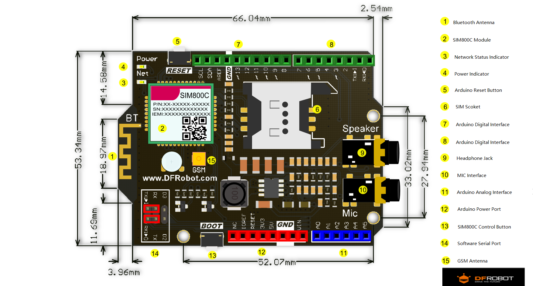
Board Overview

Note: In addition to the Boot button, the pin D12 can also be pulled high for 2s to realize module startup & shutdown.
Tutorial
Through the following tutorials, the companions can use the functions of software startup & shutdown, making and receiving a phone call, receiving/sending short messages, Bluetooth, etc. of this communication module. The companions are made to enter into the communication palace of sim800 series module easily.
| Caution: Please use 7.5~23V external power supply. |
Preparation
- Hardware
- 1 x DFRduino UNO R3
- 1 x SIM800C GPRS/GSM Shield V2.0
- 1 x USB cable
- 1 x 12VDC power
- software
- Arduino IDE click to download Arduino IDE
Startup Module
Press boot for 2s or download the following program to start up the module.
void setup()
{
  //Set the pin as the output mode
  pinMode(12,OUTPUT);
  //GSM start
  digitalWrite(12,HIGH);
  delay(2000);
  digitalWrite(12,LOW);
}
void loop()
{
}
Result
After the program is uploaded successfully, connect the serial port to TX & RX side by jumper, press reset and then you will observe that Net lamp (network status indication) - twinkles:
NET: Network status indicator:
Off——the module does not work,
64ms on/800ms off——the module fails to find the network,
64ms on/3,000ms off——the module registers the network.
Caution: The module is made to start up or shut down every time the serial port is opened or the reset is pressed; if NET lamp is found not to respond (shutdown), press Reset again to start up the module.
Making A Call
/***************************************************
 * SIM800C GPRS/GSM  Shield V1.0
 *
 ***************************************************
 * This example show you how to use SIM800C GPRS/GSM  Shield V1.0 to make a call.
 *
 * @author Dongzi
 * @version  V1.0
 * @date  2016-9-1
 * All above must be included in any redistribution
 *This code is tested on SIM800C GPRS/GSM Shield V1.0.
 ****************************************************/
#define power_key 12       //power key is connected to digital pin 12
void inint();
void power_on();
void setup() {
  inint();
}
void loop() {
  Serial.println("ATD123456789;"); //If the phone number of the other party is 123456789, please never miss the last semicolon “”;
  while(1);
}
void inint()
{
  pinMode(power_key, OUTPUT);
  Serial.begin(115200);
  power_on();
  delay(500);
}
void power_on()
{
  digitalWrite(power_key,HIGH);
  delay(1500);
  digitalWrite(power_key, LOW);
  Serial.println("AT");
  delay(300);
  Serial.println("AT");
  delay(8000);
}
- Note: Please notice the direction of the antenna during voice communication, or the voice communication quality will be affected
Result
- This program is combined with the above software startup program, and the module is controlled by sending AT instruction with arduino serial port to realize the function of making a call; “123456789” in the code. Here, you may modify any phone number that you want to dial (only if it is valid).
- It is necessary to pull up the “jumper” on the module during the burning program, because the burning code will occupy the serial port.
- After the program is burnt successfully, press “reset” for several seconds, and then there will be mobile customer service voice communication from the headset.....
Bluetooth Serial Port
- Preparation: The mobile terminal needs to download BluetoothSPP (only support Android, iOS system has not provided Bluetooth interface of below 4.0)
- The jumper is connected to D2&D3 side, and the soft serial port is used for Bluetooth communication this time.
/***************************************************
 * SIM800C GPRS/GSM  Shield V2.0
 *
 ***************************************************
 * This example show you how to use SIM800C GPRS/GSM  Shield V2.0 BT-SPP.
 *
 * @author Dongzi
 * @version  V2.0
 * @date  2016-9-1
 * All above must be included in any redistribution
 * This code is tested on SIM800C GPRS/GSM Shield V2.0.
 ****************************************************/
#include <SoftwareSerial.h>
SoftwareSerial bt_cmd(2,3);

void blue_spp();
void splitString_t(char *data);
#define power_key 12

String cmd[6]={
  "AT","AT+BTHOST?","AT+BTPOWER=1","AT+BTPAIR=1,1","AT+BTACPT=1","AT+BTSPPSEND"};
char buffer[50],power_mark=0;    // Serialbuffer and power flag

void setup()
{
  pinMode(power_key,OUTPUT);
  Serial.begin(9600);
  bt_cmd.begin(9600);
  blue_spp();
  delay(800);
  bt_cmd.println(cmd[4]);
  delay(800);
  bt_cmd.println(cmd[3]);
  delay(800);
}
void loop()
{
  data_R1();
  data_R();
}
void data_R1()  {
  if(bt_cmd.available() > 0)
  {
    int index = 0;
    delay(100);             //wait data end
    int numChar = bt_cmd.available();
    if(numChar >50)
    {
      numChar =50;
    }
    while(numChar--)
    {
      buffer[index++] = bt_cmd.read();
    }
    splitString(buffer);
  }
}
void blue_spp()
{
  bt_cmd.println(cmd[0]);
  delay(20);
  data_R1();
  delay(20);
  bt_cmd.println(cmd[2]);
  delay(200);
  bt_cmd.println(cmd[1]);
  data_R1();
  if(bt_cmd.find("ERROR"))
  {
    bt_cmd.println(cmd[1]);
    Serial.println("start again");
  }
  else
    Serial.println("bt_power_on");

}

void splitString(char *data)
{
  Serial.print("Data entered:");
  Serial.println(data);
  for(int x = 0; x < 50; x++)
  {
    buffer[x] = '\0';
  }
}
void data_R()  {
  if(Serial.available() > 0)
  {
    int index = 0;
    delay(100);
    int numChar = Serial.available();
    if(numChar >50)
    {
      numChar =50;
    }
    while(numChar--)
    {
      buffer[index++] = Serial.read();
    }
    splitString_t(buffer);
  }
}
void splitString_t(char *data)
{
  bt_cmd.println(cmd[5]);
  delay(5);
  bt_cmd.print(data);
  bt_cmd.write(0x1a);
  delay(5);
  for(int x = 0; x < 50; x++)
  {
    buffer[x] = '\0';
  }
}
Result
- This routine uses the soft serial port of arduino, and No. 2 and No. 3 digital pins are used as RX\TX of the serial port. After the program is burnt, “spp” Bluetooth serial port of the mobile terminal can realize wireless communication with serial assistant of the computer terminal through Bluetooth of the module.
image:TEL0089_Bluetooth_Arduino_monitor.png|Arduino monitor image:TEL0089_Bluetooth_Terminal.png|Android SPP Bluetooth Terminal
Instruction of Common AT Instruction
1、“AT\r\n”
Return: AT\r\n OK\r\n
Note: AT instruction test can be started up when detecting the module
2、“ATE0\r\n”
Return: ATE0\r\n OK\r\n
Note: Close the echo
3、“AT+CNMI=2,1,0,1,0\r\n”
Return: OK\r\n
Note: Set URC report format of new short message, and this command can be set after SMS ready, i.e., set after SIM800C module is informed of Arduino “SMS ready”,URC reports after receiving the short message, 1 is the serial number of the short message in the storage, +CMTI:" SM",1
4、“AT+CSCS="UCS2"\r\n”
Return: OK\r\n
Note: Set short message by using UCS2 code
5、“AT+CSQ\r\n”
Return: +CSQ:<rssi>,<ber>  OK\r\n
                   <rssi>
                      0 is less than or equal to -115dBm
                      1 -111dBm
                      2...30 -110... -54dBm`
                      31 is greater than or equal to -52dBm
                      99 is unknown or non-measurable`
                <ber> (percentage):
                     RXQUA value in 0...7 table, refer to 7.2.4 of GSM 05.08 [20]
                     99 is unknown or non-measurable
6、“ATA\r\n”
Return: OK\r\n
Note: Answer the telephone
7、“ATH0\r\n”
Return: OK\r\n
Note: Hang up
8、“AT+CLIP=1\r\n”
Return: OK\r\n
Note: Open the caller ID
9、“ATD15982373181;\r\n”
Return: OK\r\n
Note: Make a call
10、“AT+DDET=1\r\n”
Return: OK\r\n
Note: Open DTMF function
11、“AT+CMGS="00310038003600310036003300360036003500340037"\r\n”
Return: >
Note: Those in the quotation mark are UCS2-BIG codes of phone numbers. Send a short message, after returning the character “>”, input the short message to be sent, with the content code of UCS2 code (set above), then check HEX sending, send “1a”, and end with CTRL+Z(0x1A).
12、“AT+CMGR=1\r\n”
Return: +CMTI: ........
Note: Read the short message, and return the content of the short message
Description of parameters: “1” is the serial number of the short message stored in SIM800H module
13、“AT+CMGD=1\r\n”
Return: OK\r\n
Note: Delete the short message with the serial number of 1 in the storage
Note: For more AT command, please check AT Instruction
FAQ
| For any questions, advice or cool ideas to share, please visit the DFRobot Forum. |
