Introduction
-
Want to DIY an ORP meter? Need to measure the ORP value? Find it difficult to use with Arduino? Here comes an analog ORP meter specially designed for Arduino controllers and has built-in simple, convenient and practical connections and features. When done the connection according to the diagram ,it's very convenient to measure the ORP with a simple program.
-
ORP(Oxidation-Reduction Potential)is a measure of the ability of oxidation and reduction of an aqueous solution, which the relative degree of oxidizing or reducing. The unit is mV. If the xidation reduction potential is high then chemical oxidation is strong , while if the potential is lower then oxidation is weaker. The positive potential means that solution shows a certain degree of oxidation, while the negative potential means that solution shows a certain degree of reduction.
-
ORP is an important index of water quality detection, although it can not separate water quality independently, but it can be combined with other water quality indexes to reflect the ecological environment better.
-
The measuring element is an ORP composite electrode made of gold or platinum electrode. It used to measure Oxidation-Reduction Potential of the solution.
Applications
- Water quality testing
- Aquaculture
Specification
- Module Power: +5.00V
- Module Size: 40mmx27mm
- Measuring Range: -2000mV~2000mV
- Suitable Temperature: 5~70℃
- Accuracy: ±10mv (25 ℃)
- Response Time: ≤20sec
- ORP Probe with BNC Connector
- PH2.0 Interface (3 foot patch)
- Zero calibration button
- Power Indicator LED
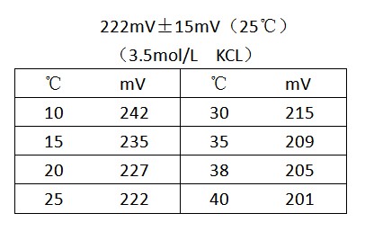
ORP Standard Solution Temperature Characteristics

Use the ORP Meter
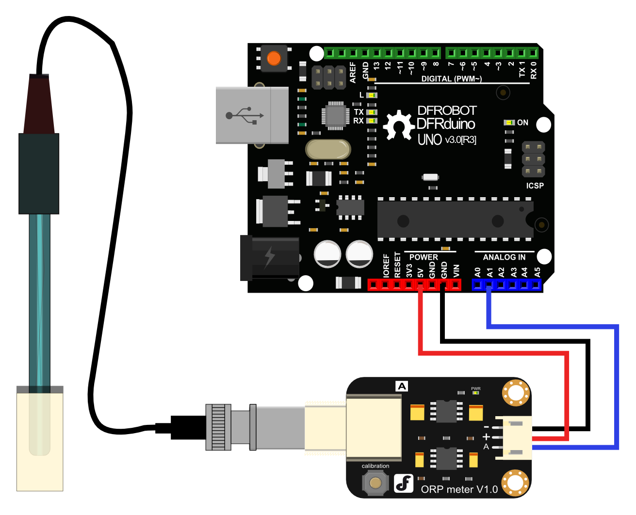
Connecting Diagram

Step to Use the ORP Meter
Cautions:
-
Please use an external switching power supply to keep the voltage as close as possible to the +5.00V. More accurate the voltage, higher the accuracy!
-
You can use the ORP electrode without calibration. Only when you doubt the ORP electrode quality or test results , you should use an ORP standard solution to check the electrode potential to determine the error.
-
Before using the ORP electrode to measure different solutions, you first should wash it. Deionized water is recommended.
-
When the ORP probe is connected to the ORP meter board,please do not press the calibration button.Or,the ORP probe may be damaged!
- Using the analog connection lines, connect the ORP meter board to analog port 1 of your Arduino controller. When the Arduino controller gets power,you will see the blue LED on board is on.
- Upload the sample code to the Arduino controller.(Note: At this time, a sentence in the sample program should be "#define OFFSET 0").
- Open the serial monitor of Arduino IDE , you will see the current ORP value.Press the calibration button and keep it pressed,you will see a small ORP vlaue printed on the serial monitor.Then according to this value, modify the offset in the sample program.For example,the serial print: "ORP: 8mV", then you should modify the sentence "#define OFFSET 0" to "#define OFFSET 8" in the sample code,then recompile the code and upload. At this time,you have completed the calibration.
- According to the graphic,the ORP electrode is connected to the BNC connector on the pH meter board.. After the calibration, the ORP electrode can measure the ORP value of the solution, through the serial monitor, you can see the current ORP value of the solution conveniently.
Sample Code
Sample code for testing the ORP meter and get the sensor feedback from the Arduino Serial Monitor.
/*
# This sample codes is for testing the ORP meter V1.0.
 # Editor : YouYou
 # Date   : 2013.11.26
 # Product: ORP meter
 # SKU    : SEN0165
*/
#define VOLTAGE 5.00    //system voltage
#define OFFSET 0        //zero drift voltage
#define LED 13         //operating instructions

double orpValue;

#define ArrayLenth  40    //times of collection
#define orpPin 1          //orp meter output,connect to Arduino controller ADC pin

int orpArray[ArrayLenth];
int orpArrayIndex=0;

double avergearray(int* arr, int number){
  int i;
  int max,min;
  double avg;
  long amount=0;
  if(number<=0){
    printf("Error number for the array to avraging!/n");
    return 0;
  }
  if(number<5){   //less than 5, calculated directly statistics
    for(i=0;i<number;i++){
      amount+=arr[i];
    }
    avg = amount/number;
    return avg;
  }else{
    if(arr[0]<arr[1]){
      min = arr[0];max=arr[1];
    }
    else{
      min=arr[1];max=arr[0];
    }
    for(i=2;i<number;i++){
      if(arr[i]<min){
        amount+=min;        //arr<min
        min=arr[i];
      }else {
        if(arr[i]>max){
          amount+=max;    //arr>max
          max=arr[i];
        }else{
          amount+=arr[i]; //min<=arr<=max
        }
      }//if
    }//for
    avg = (double)amount/(number-2);
  }//if
  return avg;
}


void setup(void) {
  Serial.begin(9600);
  pinMode(LED,OUTPUT);
}

void loop(void) {
  static unsigned long orpTimer=millis();   //analog sampling interval
  static unsigned long printTime=millis();
  if(millis() >= orpTimer)
  {
    orpTimer=millis()+20;
    orpArray[orpArrayIndex++]=analogRead(orpPin);    //read an analog value every 20ms
    if (orpArrayIndex==ArrayLenth) {
      orpArrayIndex=0;
    }
    orpValue=((30*(double)VOLTAGE*1000)-(75*avergearray(orpArray, ArrayLenth)*VOLTAGE*1000/1024))/75-OFFSET;

    //convert the analog value to orp according the circuit
  }
  if(millis() >= printTime)   //Every 800 milliseconds, print a numerical, convert the state of the LED indicator
  {
    printTime=millis()+800;
    Serial.print("ORP: ");
    Serial.print((int)orpValue);
        Serial.println("mV");
        digitalWrite(LED,1-digitalRead(LED));
  }
}
Precautions
-
Before and after measurement, it is necessary to use deionized water to wash the electrode, in order to ensure precision. When measured in thick samples, you should wash the electrode with hot deionized water and repeatedly rinsed several times to remove anything sticking to the platinum sheet specimen.
-
Passivation will occur when the electrode has been used for a long time.The phenomenon can be seen when the sensitivity gradient decreases, has slow responses, or is reading data is not accurate. At this time,you should immerse the bottom electrode platinum sheet into 0.1M hydrochloric acid for 24 hours.
-
Electrode pollution or the liquid junction jam also can make the electrode passivation. At this time,you should select the appropriate cleaning solution based on the nature of the pollutant.
-
The electrode use cycle is about one year. After aging, it should be replaced with a new electrode in a timely manner.
