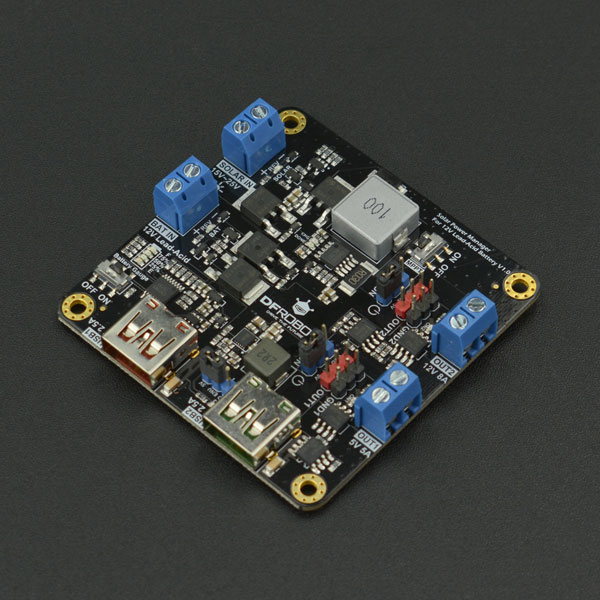
Solar Power Manager Series
Introduction
The DFRobot Solar Power Manager series are designed for IoT and renewable energy projects, providing safe and high-efficiency embedded solar power management modules for makers and application engineers. All modules in this series have MPPT (Maximum Power Point Tracking) to maximize solar energy conversion efficiency under various sunlight. A complete battery and power protection provides reliable power management for different types of solar projects.
Selection Guide
| Name | Solar Power Manager 1.0V | Solar Power Manager 5V V1.1 | Solar Power Manager Micro V1.0 | Solar Power Manager For 12V Lead-Acid Battery V1.0 ★ |
|---|---|---|---|---|
| SKU | DFR0535 | DFR0559 | DFR0579 | DFR0580 |
| Solar Power Management IC | LTC3652 | CN3065 | SPV1050 | CN3767 |
| Solar Input Voltage | 7V ~ 30V | 4.4V ~ 6V | 0.5V ~ 4V | 15V ~ 25V |
| Maximum Charge Current (Solar) | 2A (Solar/USB) | 900mA (Solar/USB) | 70mA (Solar)/100mA (USB) | 4A (Solar) |
| Topology | DC-DC Buck | Linear Regulator | DC-DC Boost | DC-DC Buck |
| Battery | 3.7V Lithium Battery | 3.7V Lithium Battery | 3.7V Lithium Battery | 12V Lead-Acid Battery |
| MPPT | 9V/12V/18V Optional | Fixed 5V | 75% Open Voltage | Fixed 18V |
| Battery Protections | Over Charge/Over Discharge/Over Current/Reverse Connection Protections | Over Charge/Over Discharge/Over Current/Reverse Connection Protections | Over Charge/Over Discharge/Reverse Connection Protections | Over Charge/Over Discharge/Reverse Connection Protections |
| Output Protections | Short Circuit/Over Current/Over Heat Protections | Short Circuit/Over Current Protections | Short Circuit/Over Current Protections | Short Circuit/Over Current/Over Heat Protections |
| USB Charge IN | Yes | Yes | Yes | No |
| USB OUT | 5V 1.5A | 5V 1A | No | 5V 2.5A X2 |
| Regulated OUT | Three Regulated Outputs 3.3V 1A;5V 1.5V;9V/12V 0.5A |
One Regulated Output 5V 1A |
One Regulated Output 3.3V 90mA |
Two Outputs 5V 5A; 12V 8A |
| Dimension | 78.0mm×68.0mm | 33.0mm×63.0mm | 30.0mm×30.0mm | 68.0mm×68.0mm |
| Features | A complete multifunction solar power management module. Applications: Small Solar Street Lamp, Solar Powered Robots For 9V/12V/18V Solar Panels within 20W |
A small and easy-to-use 5V solar power management module. Applications: Solar Power Bank, Solar Environment Monitors For 5V Solar Panels within 10W |
A micro power solar power management module for low-power sensors and controllers. Applications: Wireless Sensor Network, BLE iBecon For 1V/2V/3V Solar Panels within 0.5W |
Medium power solar management module for 12V lead-acid batteries. Applications: Street lighting, intelligent agriculture, environmental monitoring station For 18V Solar Panels within 100W |
Introduction
Solar Power Manager For 12V Lead-Acid Battery is a medium-power high-efficiency solar power management module, which is able to charge a 12V lead-acid battery with a maximum of 4A using a standard 18V solar panel. It is suitable for applications within 100W, such as 12V lighting equipments, security monitoring, small robots, pumps or environmental monitoring stations. It features as MPPT(Maximum Power Point Tracking) function, maximizing the output power of solar panels under various sunlight. Compared with common PWM solar controllers, it can improve charging performance by 10%-30%. Benefited from its small size and light weight, it is easy to embed it in your projects. The module provides dual high-power outputs 5V 5A (OUT1) and 12V 8A (OUT2) and dual USB outputs 5V 2.5A (USB1/USB2). Except USB1, all outputs can be turned ON/OFF by I/O pins of most controllers (3.3V/5V compatible). This feature helps to dynamically power loads and reduce power consumption. Various protection functions are also employed to ensure the safety and stability of the solar systems.
Features
- Constant voltage (18V fixed) MPPT algorithm, maximizing solar energy conversion
- Designed for standard 18V solar panels and 12V lead-acid battery
- Multiple high efficiency outputs for 12V or 5V large power devices
- Support three USB charging protocols
- Full protection functions, a safe and high efficiency power module
- A variety of status indicators, system status at a glance
Specifications
- Solar Power Management IC: CN3767
- Solar Input Voltage (SOLAR IN): 15V~25V
- Battery Input (BAT IN): 12V Lead-Acid Battery
- Charge Current: 4A Max Trickle Charging, Constant Current, Constant Voltage, Float Charging Four Stages Charging dedicated for 12V Lead-Acid Battery
- Float Charge Voltage: 13.55V
- Constant Voltage Stage: 14.8V
- Over-discharge Protection Voltage: 10.8V
- Over-discharge Protection Release Voltage: 11.8V
- Solar Charge Average Efficiency (18V SOLAR IN): 94%
- OutputsNote1: OUT1 5V 5A, OUT2 12V 8A, USB1 5V 2.5A, USB2 5V 2.5A
- USB1/USB2 Support Three USB Charge ProtocolsNote2
- Apple 2.4A:DP=2.7V,DM=2.7V
- SAMSUNG 2.0A:DP = 1.2V,DM =1.2V
- BC1.2:DP=DM=0V (Short)
- OUT1/USB1/USB2 Efficiency: 90%@10%Load, 93%@50%Load, 92%@90%Load
- OUT2 Efficiency: 99%@10%Load, 98%@50%Load, 97%@90%Load
- Operating Current: <4 mA
- Protection Functions
- SOLAR IN: Backflow/Reverse Connection Protections
- BAT IN: Over-discharge/Over-charge/Reverse Connection Protections
- OUT1-2/USB1-2: Short Circuit/Over Current/Over Heat Protections
- Operation Temperature: -40℃~85℃
- Dimension: 68.0mm*68.0mm
Attention
**Note 1:**OUT1/USB1/USB2 shared 5A current driving capacity (peak current 8A), that is, the total output power of the three outputs should not exceed 5V*5A=25W (peak 40W).Note 2: It does not guarantee support for all mobile phone or tablet PC. Please consult the device manufacturers or retailers for detail. If the mobile phone or tablet does not support the above USB charging protocol, the device usually limits the charging power to 5V*1A=5W for security. This is not caused by the failure of the USB output or insufficient output capability.
Applications
- Street lighting
- Intelligent Agriculture
- Environmental Monitoring Station
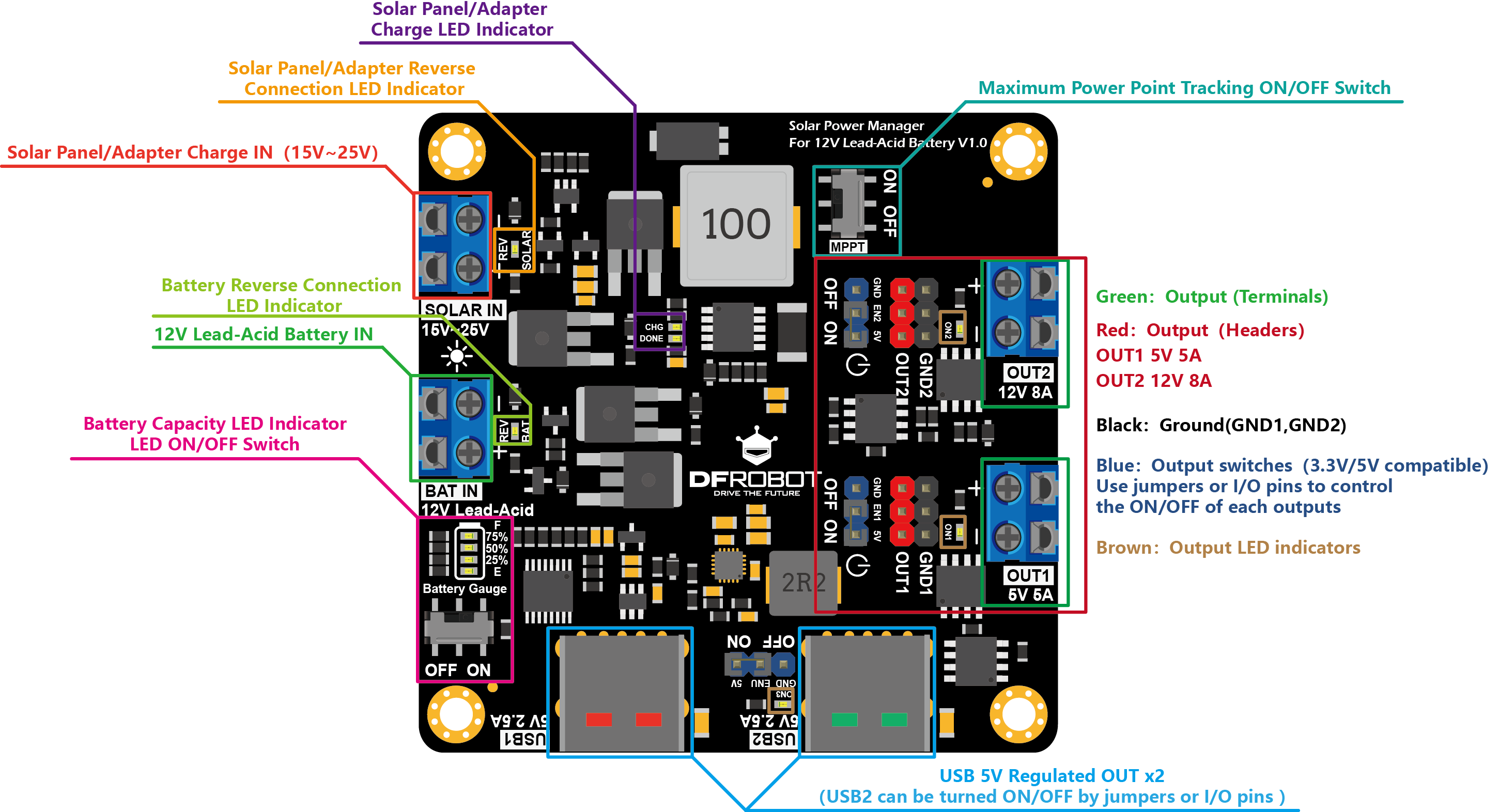
Board Overview
Quick Start
Build a solar powered system
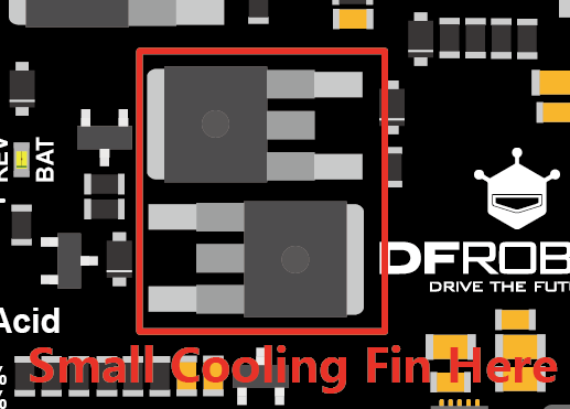
- Stick the black aluminum cooling fin (50mm*50mm) within the frame marked “Cooling Fin” at the bottom of the module through the blue thermal silica gel. Stick the black small aluminum cooling fin (7mm*7mm) through the blue thermal silica gel on the surface of the two FETs near the BAT IN terminal as shown below.
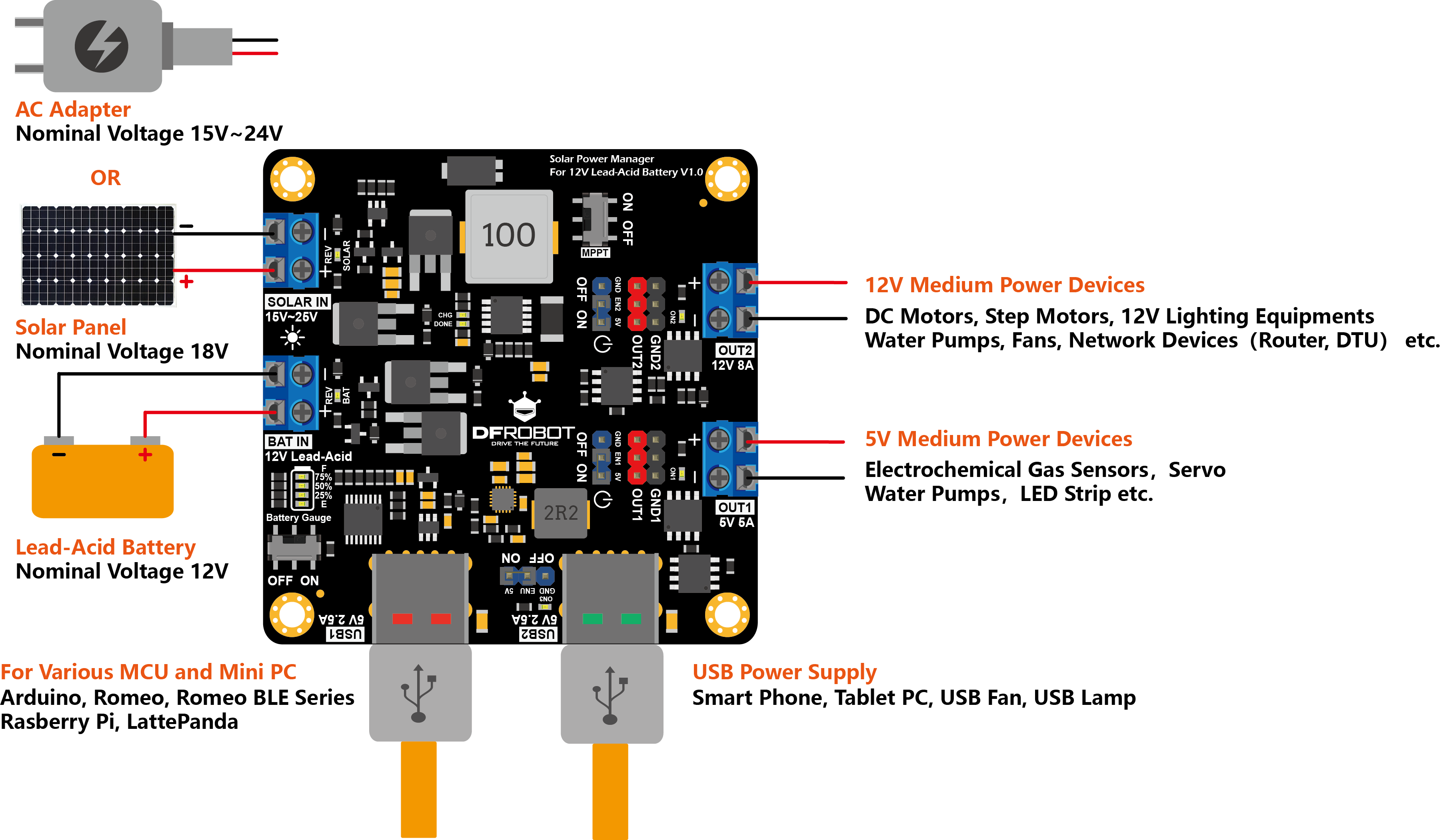
- Connect a 12V lead-acid battery to the BAT IN terminal.
- Connect a 18V rated solar panel to the SOLAR IN terminal..
- Connect the controller such as Arduino or Raspberry Pi to USB1, and connect the load (mobile phone, motor, lighting equipment, etc.) to OUT1-2 or USB2. Note that you need to plug the jumper to ON of the blue header to turn on the output (plug to OFF to turn off).
Detailed Description
Maximum Power Point Tracking, MPPT
The MPPT (Maximum Power Point Tracking) can ensure the solar panel output power maintains at its maximum under different loads and sunlight, maximizing the conversion efficiency.
We can identify the short circuit current ISC and the open circuit voltage VOC from the cross points of the I/V curve (green) with x and y axis respectively. The ISC and VOC grow larger with the illumination increasing. With the output voltage VPANEL growing, the output current IPANEL gradually decreases and then jumps down after crosses a special point VMP, the maximum power voltage. By multiplying the voltage and current, which obviously results in power, and take the output voltage as the x axis, we obtain the P/V curve (blue). The output power PPANEL reaches its peak when the output voltage is at VMP. Although the maximum power increases with illumination, the VMP changes little. Therefore, we may approximately take the VMP as a constant for a specific solar panel under different illumination. This value is usually 70%~80% of the open circuit voltage VOC, i.e. VMP=(70% ~ 80%)*VOC.
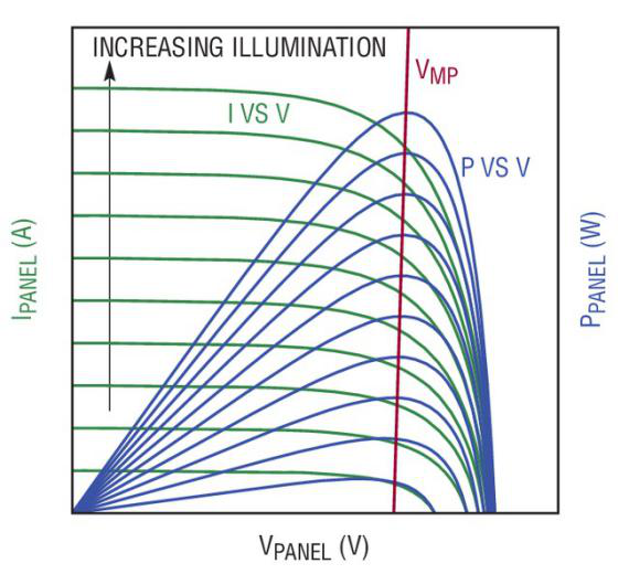
The CN3767 solar power management IC employed in this module uses a constant voltage MPPT algorithm to control the solar output voltage around 18V to maximize the output power of the 18V solar panel. Compared with PWM solar controller, it can increase the output power of the solar panel by 10%-30%.
Charging Cycle
The module safely and quickly charges lithium battery through three phases: trickle charge, constant current charge, constant voltage charge.
- Trickle charge: Since the internal resistance of the lead-acid battery becomes high when the voltage is low, it is not a good manner to charge with large current at the beginning. Otherwise, the battery temperature rises and the battery life is lowered. When the battery voltage is lower than the trickle charge threshold voltage of 11.1V, the module enters the trickle charge phase, charging the battery at 17.5% of the maximum charge current up to 700mA, until the battery voltage is higher than 11.1V.
- Constant current charge: When the battery voltage is higher than 11.1V, the module enters the constant current charging phase, and the battery is charged with a constant current up to 4A. During the phases of trickle and constant current charge, the CHG red LED turns ON and the DONE green LED turns OFF.
- Constant voltage charge: When the battery voltage is closing to the charge cut-off voltage of 14.8V, the module enters the constant voltage charge phase. The module continues to charge the battery with a constant voltage, and the charging current gradually decreases. When the charging current drops to 38% of the maximum charging current of 1.52A, the charging ends and the module enters the float charge phase. The CHG red LED turns OFF and the DONE green LED turns ON.
- Float charge: The module maintains 13.55V to compensate for battery energy loss due to battery self-discharge or load.
- Automatic recharge: During floating state, if the module input source (SOLAR IN) is not powered off and the battery voltage decreases due to self-discharge or load, when the battery voltage drops to 83.95% of the constant voltage charging voltage of 12.42V, a new charging cycle will automatically begin.
.png)
Solar Panel Selection
The SOLAR IN port can be connected to standard solar panel with a nominal voltage of 18V. Taking into account the size, weight, price of the solar panel and the maximum charging current of the module, a solar panel with a rated power no more than 100W is recommended.
Battery Selection
This module adopts the four-stage charging mode for lead-acid batteries. The voltage in constant voltage stage is 14.8V, and the voltage in the float charging stage is 13.55V. Although the BAT IN port can be connected to the 12V lead-acid battery, such batteries have many subdivision types
- FLA (Flooded Lead Acid)
- AGM (Absorbent Glass Mat battery)
- Gel Battery
The specific parameters of these batteries are not all the same. Users should pay attention to two parameters of the battery: float use voltage range and cycle use voltage range. 13.55V should be within the float use range and 14.8V should be within the cycle use range. If the battery does not indicate these parameters, please consult the battery manufacturer or retailers.
Warning
- Do not use this module for other types of batteries except for 12V lead acid batteries.
- Do not use the battery if the above battery parameters do not match the module charging voltage or if you are not sure about the parameters of the battery.
Muti-controllable Outputs
The module has two high-power outputs (OUT1=5V 5A, OUT2=12V 8A) and two USB outputs (USB1=5V 2.5A, USB2=5V 2.5A). Among them, OUT1/USB1/USB2 share the 5A current (peak current 8A), that is, the total output power of these three outputs should NOT exceed 5V*5A=25W (peak 40W). If only one of the OUT1/USB1/USB2 output is used alone, each output has a 5V 5A output capability (ie, if USB1 is used alone, it can continuously output 5V 5A; if USB2 is used alone, it can also output 5V 5A) . When USB1 is powered on, it cannot be turned off and has no output indicator.
Users can use jumpers or I/O pins to control the ON/OFF of OUT1/OUT2/USB2. Insert the jumper into ON of the blue header. The corresponding output will be turned on (the green indicator turns on), and will be turned off when inserted into OFF header. Pull out the jumper and connect any digital I/O pin and GND to the pins on blue header labeled EN and GND (OUT1 corresponds to EN1, OUT2 corresponds to EN2, USB2 corresponds to ENU). Set the I/O pin to HIGH to turned on the output. Set to LOW to turned off. This feature is especially useful in water pumps, solar street lights or smart agriculture, which dynamically switch lighting or pumps depending on ambient light or soil moisture.
Attention
- GND1 and GND2 are not the same as the system ground GND. When the OUT1 or OUT2 output is turned on, the corresponding GND1 or GND2 is connected to the system ground GND, respectively. When OUT1 or OUT2 output is turned off, GND1 and GND2 are left floating (disconnected from GND).
- The 5V pin on each blue header has only 100mA drive capability. This pin unconditionally output 5V regardless of the protection mode (such as over current protection or over discharge protection). It is not recommended to drive device with this pin.
LED Indicators
There are four types of LED indicators indicating the operation status of different parts of the module:
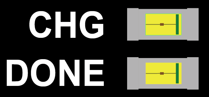
- Charging LED Indicators:When the battery is charged with SOLAR IN, the CHG indicator (red) lights up, and when the battery is fully charged (in the float charging stage), the DONE indicator (green) lights up and CHG turns off.
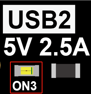
- Output LED Indicator: The ON1-ON3 indicator (green) indicates the output status of the corresponding OUT1/OUT2/USB2, respectively. When the output is turned on, the light is on. When turned off, the light is off. USB1 has no status indicator and cannot be turned off. As long as there is input on either BAT IN or SOLAR IN, USB1 outputs 5V.

- Battery Fuel Gauge LED indicator: the four different color LED indicators show the remaining battery power. These indicators can be turned off to save power by the switch below, when the module is to be left unattended for a long time. The relationship between the battery indicator and the remaining power is shown in the following table:
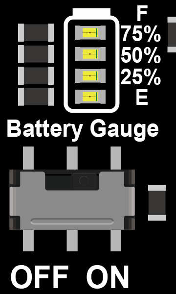
| Capacity | Red(E) | Yellow(25%) | Green(50%) | Blue(75%) |
|---|---|---|---|---|
| Power>75% | ON | ON | ON | ON |
| 50%<Power≤75% | ON | ON | ON | OFF |
| 25%<Power≤50% | ON | ON | OFF | OFF |
| Power≤25% | ON | OFF | OFF | OFF |
| Empty (Over-discharge Protection) | OFF | OFF | OFF | OFF |
- Reverse connection LED indicator: when the battery is reverse connected at the BAT IN or SOLAR IN, the corresponding orange LED REV BAT or REV SOLAR turns ON, informing the user a reverse connection error.

Protection Functions
-
Reverse connection protection: On the BAT IN and SOLAR IN, the reverse connection protection circuit prevents the reverse voltage from damaging the module and the REV indicator will turn on to inform the user.
-
Output protection: All output ports have over current/short circuit protection.
- For OUT1/USB1/USB2, when either of the output currents exceeds 8A or the output is shorted, these outputs will be turned off. To restore the OUT1/USB1/USB2, you need to reboot the module. Disconnect SOLAR IN and BAT IN in turn, and then restore the output by reconnecting battery to BAT IN and solar panel to SOLAR IN in turn.
- OUT2 can be seen as a battery output with over current and over discharge protection. Open circuit output voltage is the same as the battery voltage. When the output is fully loaded, due to the internal loss, there will be a voltage drop about 0.7V~0.9V from BAT IN to OUT2. Inserted the jumper to the ON header of OUT2 will turn on this output without over current/short circuit protection. '''Inserted the jumper to the ON header of OUT2 and then pull it out. ON2 remains on and OUT2 enters over current/short circuit protection mode. '''In this protection mode, when the OUT2 output current exceeds 9A~10A, it will be immediately turned off, the corresponding ON2 indicator is off to. To restored OUT2, Inserted the jumper to the ON header again. Pull the jumper out. Enter the over current/short circuit protection mode. If the current continues to exceed 9A~10A, the OUT2 output will automatically turn off within 30s-60s. If you need to use the I/O pin to dynamically turn OUT2 on or off (here assumed this I/O to be pin_EN2), and let OUT2 enter the over current / short circuit protection mode, you can refer to the code as follow (take Arduino as an example). Connect the I/O pin and GND of the MCU to EN2 and GND on the blue header of OUT2 respectively. Set the pin to output mode and outputs a HIGH for about 1 ms, and then set it to the high impedance (high-z) input mode. Such mode float EN2 pin, but the ON2 indicator remains on, which indicate OUT2 has entered the over current/short-circuit protection mode. If EN2 is pulled HIGH or LOW for the whole time, OUT2 will remain ON or OFF and will not enter protection mode.
pinMode(pin_EN2, OUTPUT);
digitalWrite(pin_EN2, HIGH);  //Set to HIGH to turn OUT2 on
delay(1);
pinMode(pin_EN2, INPUT);    //Set as INPUT (high-z) to float EN2 pin. OUT2 will remain on and enter protection mode
- Battery Over-discharge Protection:The battery over-discharge protection voltage is 10.8V. When the battery voltage drops due to discharge or the BAT IN input voltage is lower than this value, the over-discharge protection circuit will be triggered to prevent the battery from further discharging. However, battery can still be charged. When the battery is charged until it exceeds the over-discharge protection release voltage of 11.8V, the over-discharge protection circuit again turns on the discharge path for the battery.
Heat Dissipation Enhancement
Although the cooling fin attached to the module can effectively enhance the heat dissipation during high current charging and discharging, when the module needs to work in hot outdoor or full load for a long time, its lifespan may be shortened due to long time operation in high temperature. Excessive temperature can also lower the over-current trigger threshold of OUT2, or even cause OUT1/USB1/USB2 to turn off due to thermal protection. If the module needs to run in such high temperature or high load condition for a long time, it is recommended that users use the common low-power silent cooling fan (commonly used in PC) to enhance the heat dissipation to extend the module’s life-span and improve its stability.
Application Examples
Use an AC Adapter to Charge a 12V Lead-acid Battery
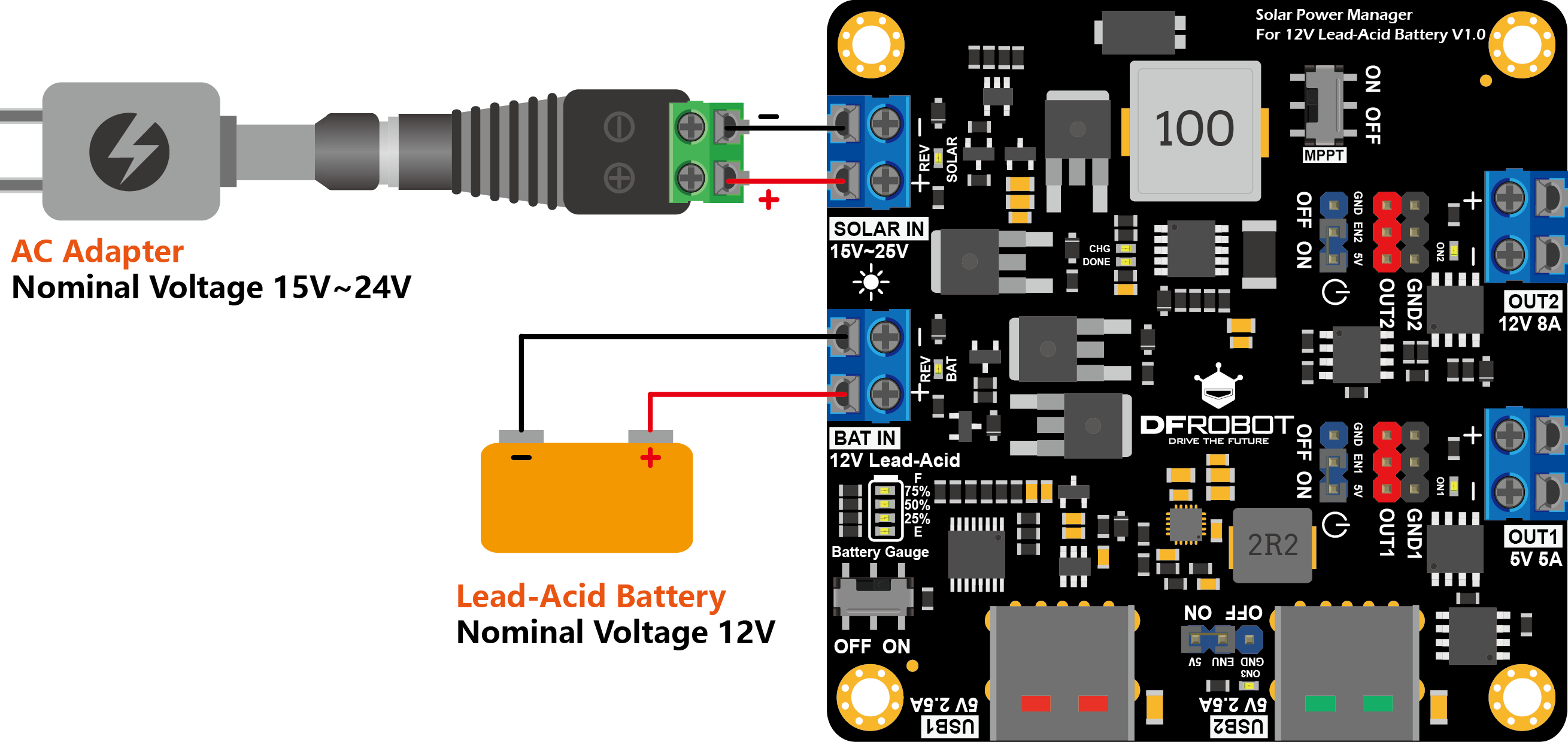
It is possible to use this module to charge a 12V lead-acid battery at 4A with ''' a notebook AC adapter (usually rated 19V or 20V ) rated power no less than 65W ''' . Switch the MPPT to OFF to disable MPPT function. Connect the output of the AC adapter to the female DC power jack adapter and wire the SOLAR IN to the terminal end of the adapter (as shown followed).
Drive Multiple Motors with Romeo
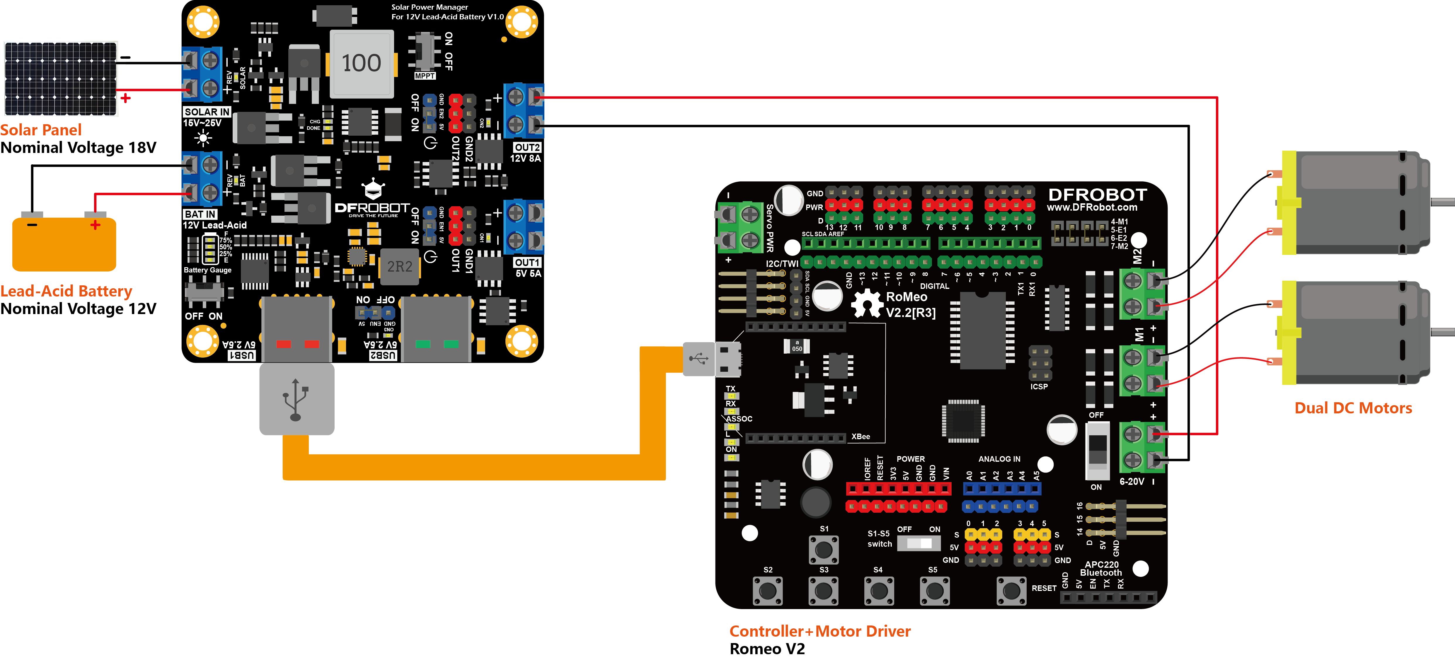
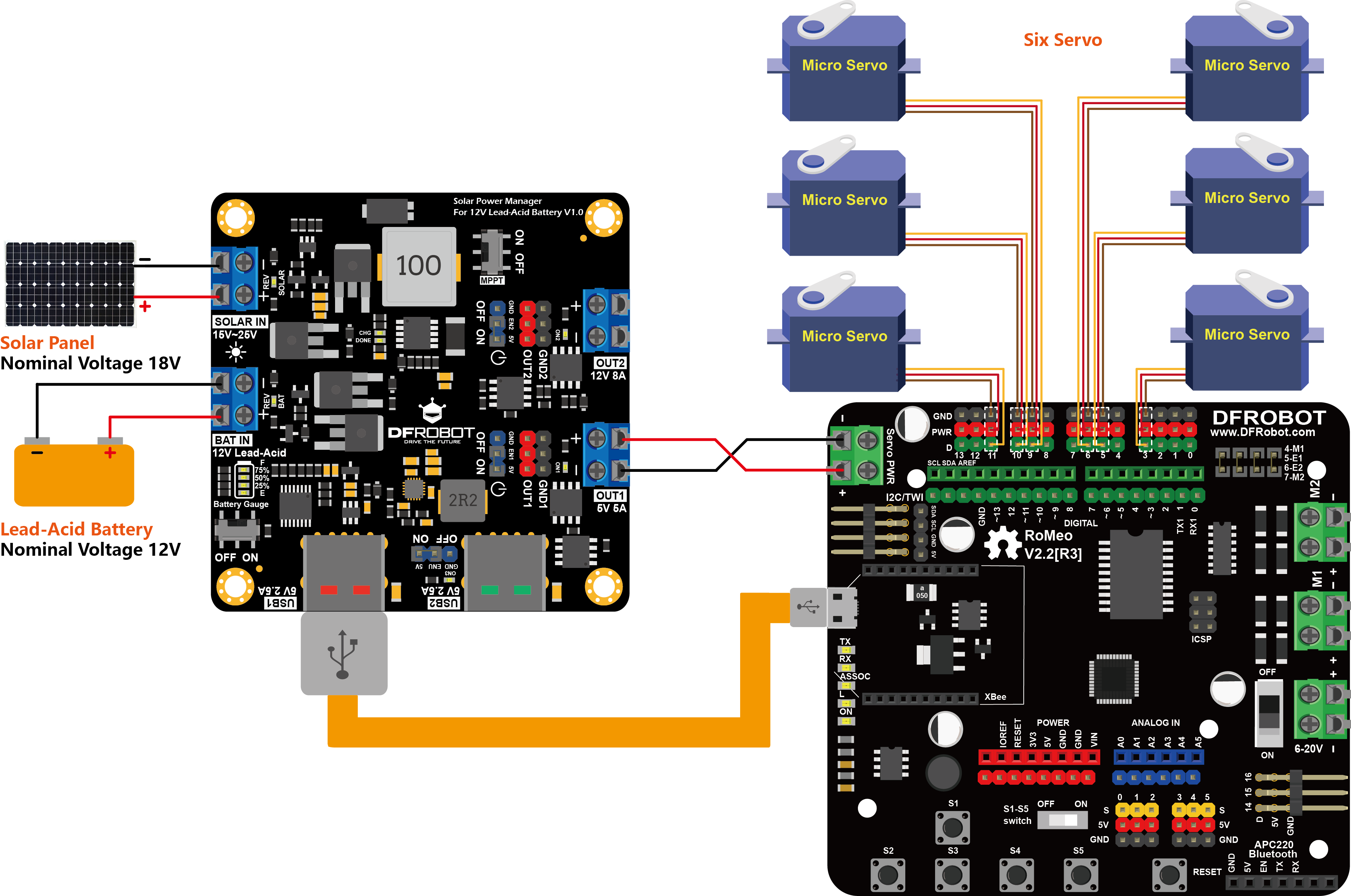
When using Romeo to build a robotic, in order to drive multiple servos or high-power DC motors, you usually need a power adapter with a external power supply, a Lipo battery, or even a 12V lead-acid battery. With the module's powerful output capability, it can easily drive six servos and two additional DC motors, while providing a full range of protection for the battery. When the power is exhausted, it can also be charged by the power adapter. (Of course, solar panels can also be used to build solar-powered robots or trolleys), which is ideally suited as an embedded power management module for various types of systems driven by 12V batteries.
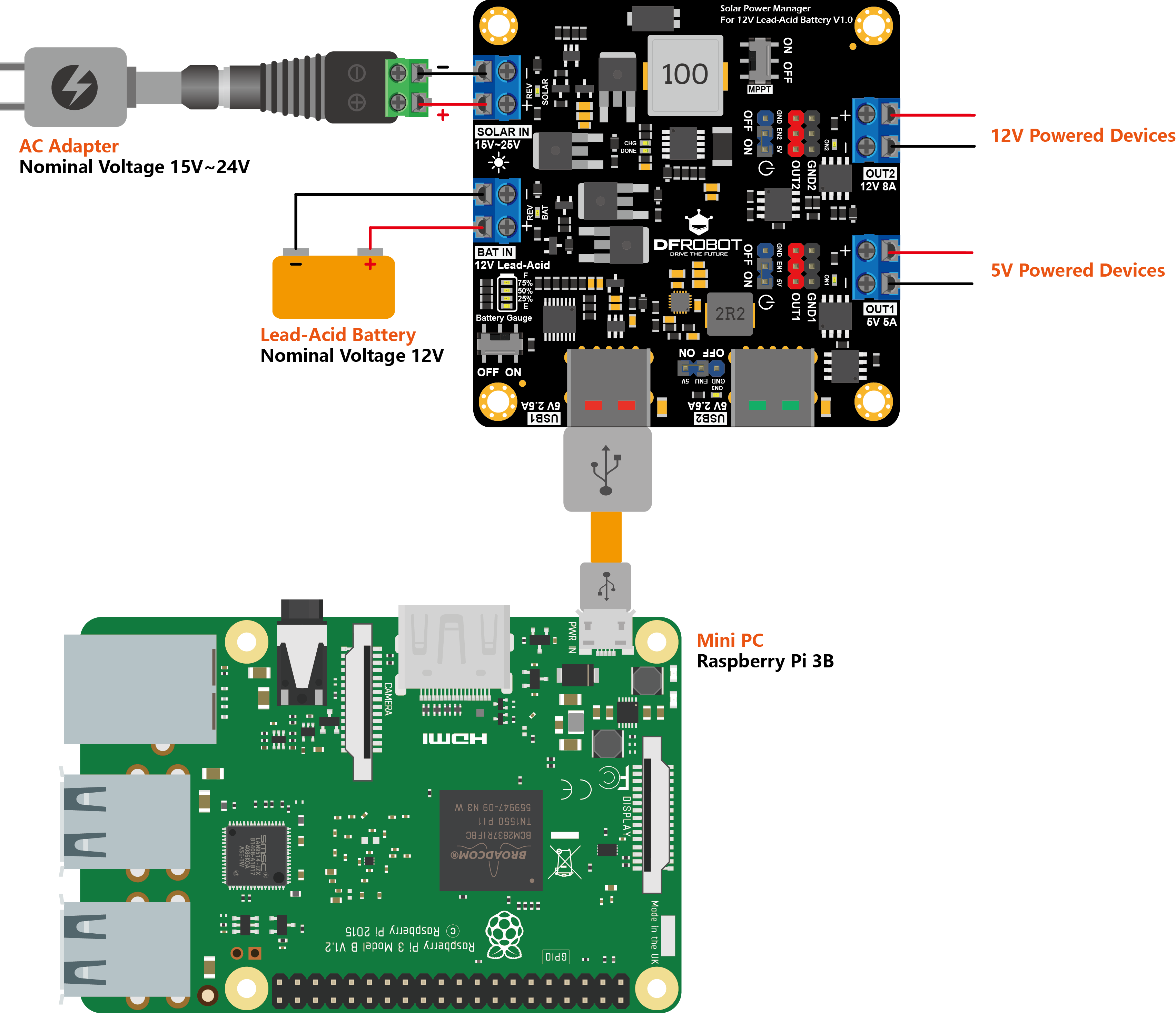
Build a UPS for Mini PC
Common Mini PCs such as Raspberry Pi, Latte Panda, or various ARM core-based development boards are widely used for various projects. In some projects, the mini PC may be part of a small server or security monitoring system. For such applications, the unexpected power outage of the power grid may cause the failure of the whole network. The Traditional UPS solution is large and cumbersome, and the cost is relatively high. However, many commercial power bank cannot charge (5V IN) the battery while discharge (5V OUT) at the same time. Also, they cannot power all 12V devices (such as routers, DTUs, security cameras). Thus they are not suitable as a UPS in these applications. With this module, a small UPS can be built. When the external power supply is interrupted unexpectedly, the module automatically switches to the battery power supply to provide continuous power supply to the system to avoid power failure.
FAQ
For any questions, advice or cool ideas to share, please visit the DFRobot Forum.
Version iteration record
V2.0 Optimize the peripheral circuit design of CN1185, and solve the problem that the MOS tube may heat up abnormally when OUT2 is in use.
