This wiki has been stopped updated. Please check WIFI Shield V3 PCB Antenna SKU:TEL0078 for the latest one.
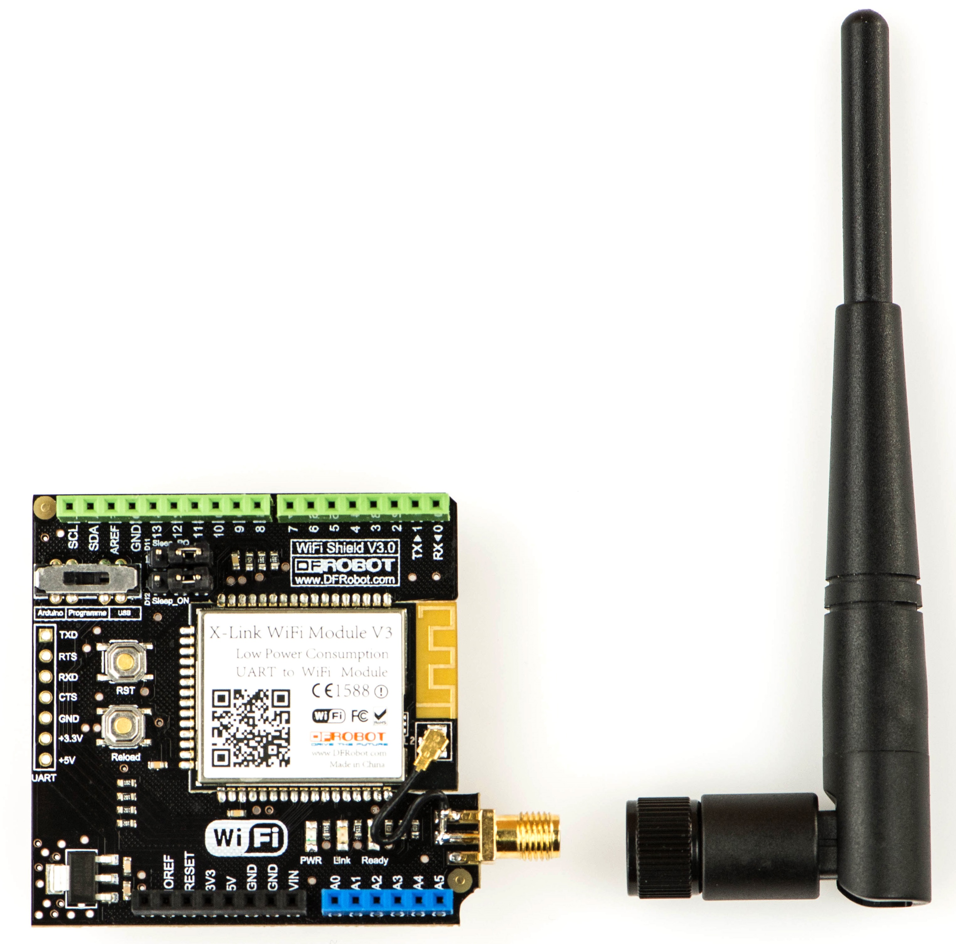
Introduction
This WiFi shield supports AP+STA dual mode, and connecting to the router WiFi network is very convenient. You only need a mobilephone or PAD to log in the AP network of this module(similar to the way log in the router).After logging in the module,it can be set to connect the WIFI network.(Don't need the AT command to set the module,which is often very complex.)
This module uses the dynamic power management to achieve low power consumption (standby: <80uA; normal mode:average:8mA; peak:200mA).If used to design products, not only relatively low power consumption, but also can be set to standby mode. The module provides UART(TTL) to IEEE802.11b/g/n wireless communication. IEEE802.11n is a newest wireless transmission protocol approved by IEEE.It has many features such as: higher transmission speed, wide coverage, strong compatibility, more safety and so on. At present, many wireless electronic equipment manufacturers have been applied this standard(IEEE802.11n) in a large number of products. Through this module, any device with UART can easily set up a wireless network to realize the remote management and control.
Specification
- Working voltage:5V
- Frequency range:2.4 - 2.497GHz
- Output power:16dBm
- Transmission rate:54Mbps - 1Mbps
- Transmission distance:<150M
- Size:55mm×53mm×11mm
- Weight:about 40g
- Support IEEE 802.11b/g/n
- Support AP,Client,Gateway and UART to WLAN mode and so on
- Support DHCP,automatic access to IP;Support allocating IP to salve device in AP mode
- Support network protocol:TCP/UDP/ARP/ICMP/HTTP/DNS/DHCP
- The optional working mode:TCP Server/TCP Client/UDP;Support up to 32 Client in TCP Server mode
- Support most of WIFI encryption algorithm:WEP/WAP-PSK/WAP2-PSK/WAPI;Type of encryption:WEP64/WEP128/TKIP/AES
- Support transparent UART/protocol data transmission mode;Up to 1M cache space;Highest baud rate:460800bps
- Support UART(TTL) to wireless applications
- Drag down the level of the Reload IO pin for 3 sencods,you can restore factory settings.So do not worry about the wrong settings.
- Support running in AP mode and the node (Station) mode;The real hardware AP, so Android can directly access it.
- Provide AT command configuration
- Provide the friendly web configuration page,and can be configured by webpage
- Serial frame delay and the amount of data can be set.
- Support routing/bridge mode network architecture
- Designed by standard Arduino stack, and can be easily put on the standard Arduino, MEGA, Romeo board or shield
Pin Out
LED indicator:
- Power: Power supply OK
- Link: Connected to the WiFi network completed
- Ready: Initialization completed
Buttons on the shield:
- RST: Reset the Arduino controller
- Reload: When press it down more than 3 seconds and loosen it,the WIFI shield will restore factory settings.
Switches on the shield:
- Arduino: Establish the communication between WIFI shield and Arduino
- Programme: Disconnect the communication between WIFI shield and Arduino
- USB: Establish the communication between WIFI shield and the USB interface, which can be directly send and receive data from the USB interface.
Jumpers on the shield:
-
D11 Sleep_RQ :Jump to D11 pin,dormancy control input of the WIFI shield.When in the normal working state, set it to low level, and after 5 seconds,set it to high level, the WIFI shield will enter a state of dormancy;When in the dormancy state, set it to low level, and after 2 seconds,set it to high level,the WIFI shield will enter the normal working state.When not using this pin,jump to the other side of the D11 font.
-
D12 Sleep_ON :Jump to D12 pin,dormancy state output pin of the WIFI shield.The electrical level of this pin is used to indicate working state of the shiled.When low,the shield is in sleep mode;When high,the shield is in the normal working state.When not using this pin,jump to the other side of the D12 font.
Tutorial
AP+STA Mode
Work In TCP-Client
This WIFI shield can set up an AP network. You can use your computer or mobile phone or PAD to log in this AP network to set the parameters of this WIFI shield. Compared with other WIFI shileds, AT commands are not need. So it is very easy and convenient to use this WIFI shield.
NOTE:The AP network set up by this WIFI shiled only allow one device to log in.
1.Put this WIFI shield on the Arduino board and connect to your computer with USB cable.The computer can access a wireless network.Then you should upload a program independent of UART, such as Blink. When programming, the switch should be turned to PROGRAMME. When done, it should be turned to USB.
2.Search for wireless network in the computer,and then you should see the network whose name is DFROBOT_WIFI_SHIELD_V3. Connect to it.Then you can log in the AP network by the Internet Explorer.Input 10.10.100.254 in the address bar,then input the user name and the password,you will log in the AP network.This process is similar to log in a router.
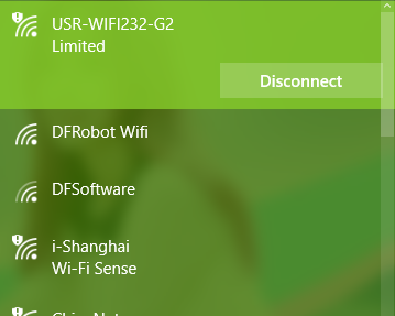
Factory setting of this WIFI shield:
SSID :DFROBOT_WIFI_SHIELD_V3
IP Address :10.10.100.254
Subnet Mask:255.255.255.0
User Name :admin
Password :admin
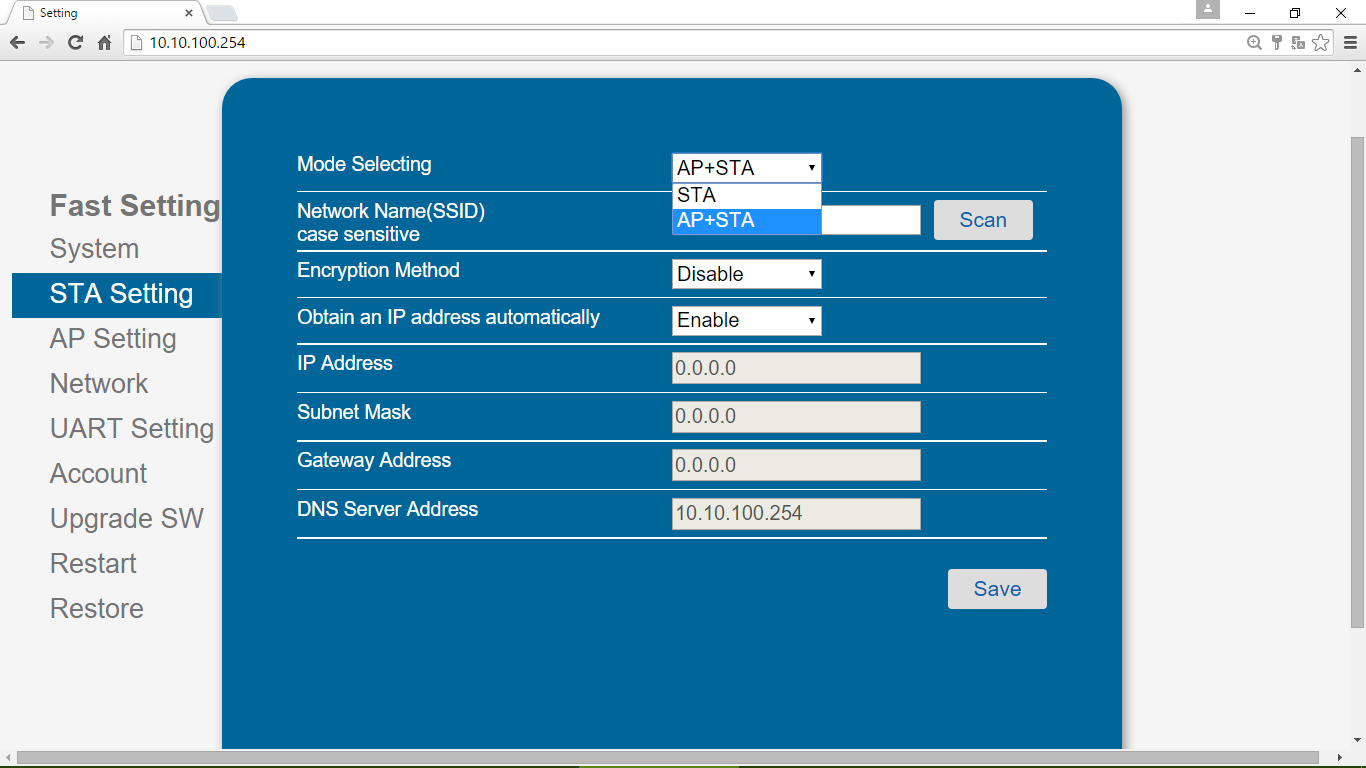
3.In the option of Work Mode,please select the mode: AP+STA mode.
Note :You should click the save button after each setting.If you need other setting,click back button and continue your other settings.Finally restart the shield, the settings will be taken effect.
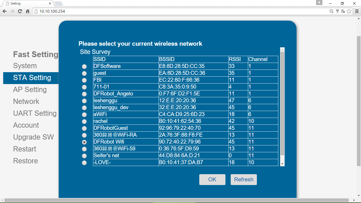
4.In the option of STA Setting,click the scan button to search the wireless you want to connect.In this example,I want to connect to DFRobot WIFI.
5.Then input the wireless password and click the save button.
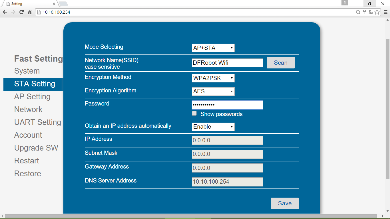
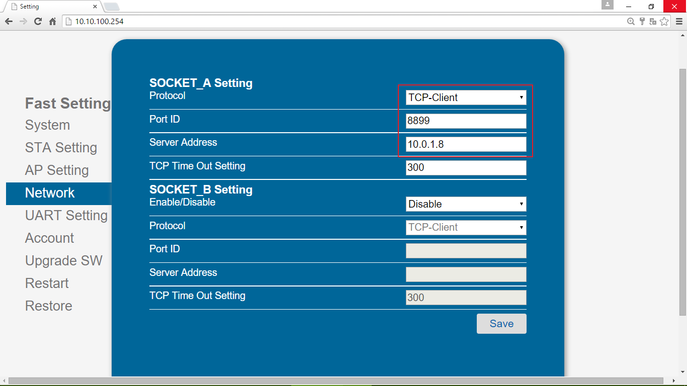
6.In the option of Other Setting,you should revise the network parameters setting as the following picture.
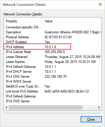
Note:The server address should be in the same IP address range of the wireless network!In this example,it is 10.0.1.8 .(It is your computer's IP address, using as TEL0078's Server.) |
Protocol :TCP-Client
Port ID :8899
Server Address :10.0.1.8
TCP Time Out Setting:300
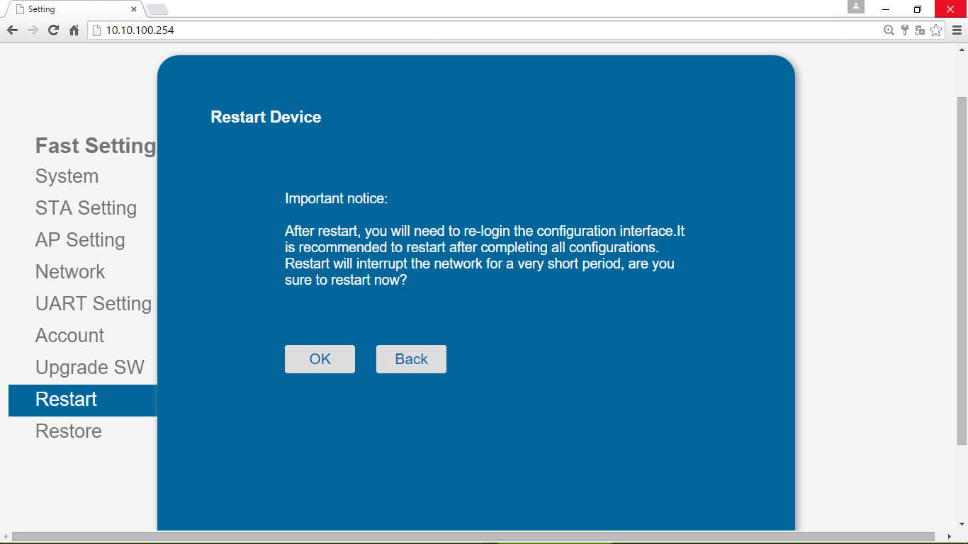
7.Restart the shield.
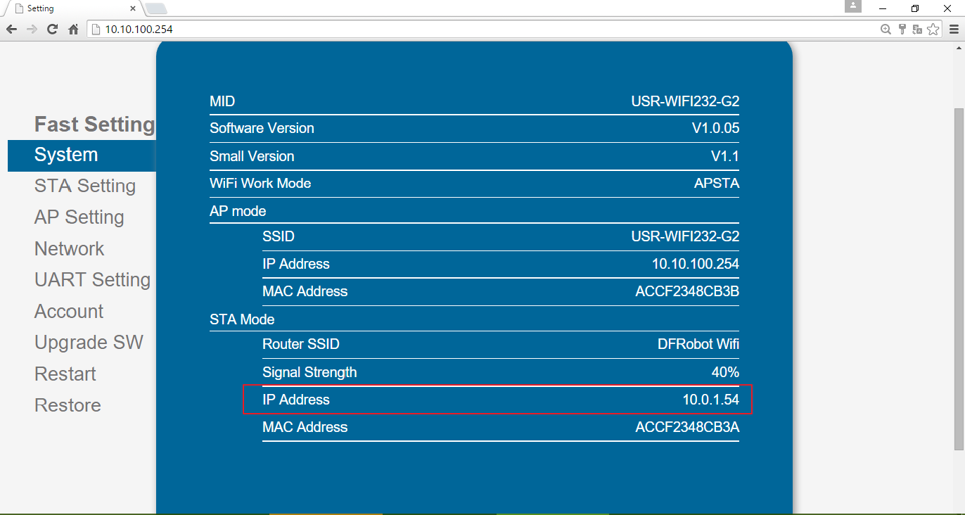
8.Search the wireless network whose name is DFROBOT_WIFI_SHIELD_V3 and connect to it.You can log in the AP network by the Internet Explorer to see the parameters.If the WIFI shiled connect to the WIFI network successfully,the LINK LED will be ON and also you can see the parameters such as Router SSID,Signal Strength,IP Address and MAC Address.
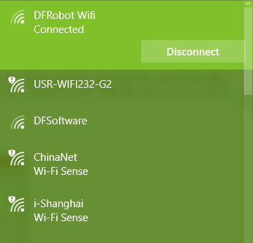
9.Let your computer connect to the wirelss network which has connnected by the WIFI shiled.In this example,I connect to DFRobot WIFI.
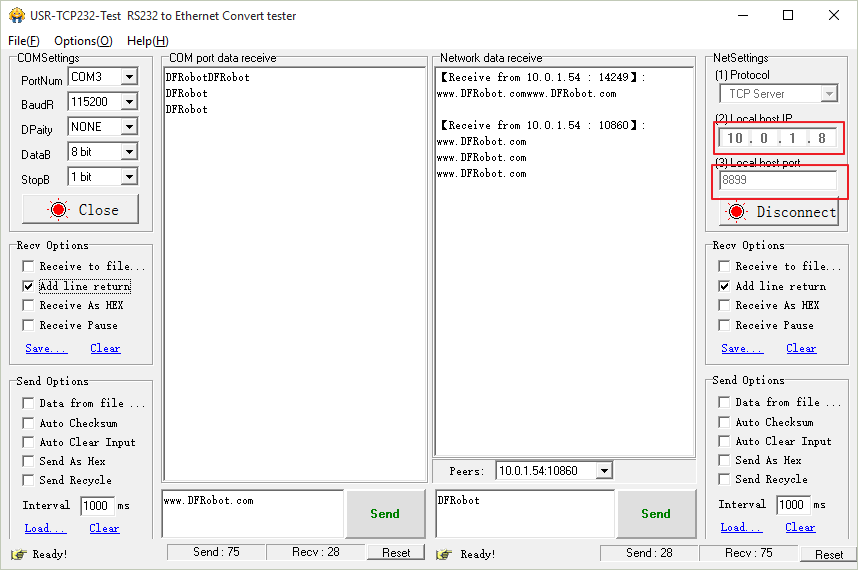
10.Open the software USR-TCP232-Test RS232 to Ethernet Convert tester.Choose the PortNum of the arduino COM(you can look up the portnum in the device manager) and click the open button.After that,you should revise the NetSettings.The protocol is TCP Server and the Local host port is the PORT ID we just set.That is 8234.Click the connect button.You will find that data can be received and sended between UART and network port.
Note:When you use the software USR-TCP232-Test RS232 to Ethernet Convert tester,you'd better close the firewall! |
Working In TCP-Server
1.Put this WIFI shield on the Arduino board and connect to your computer with USB cable.The computer can access a wireless network.Then you should upload a program independent of UART,such as Blink.When programming,the switch should be turned to PROGRAMME.When done,it should be turned to USB.
2.Search for wireless network in the computer,and then you should see the network whose name is DFROBOT_WIFI_SHIELD_V3. Connect to it.Then you can log in the AP network by the Internet Explorer.Input 10.10.100.254 in the address bar,then input the user name and the password,you will log in the AP network.This process is similar to log in a router.
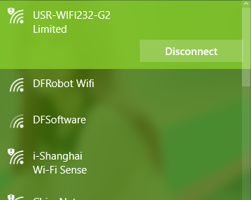
3.In the option of Work Mode,please select the mode: AP+STA mode.
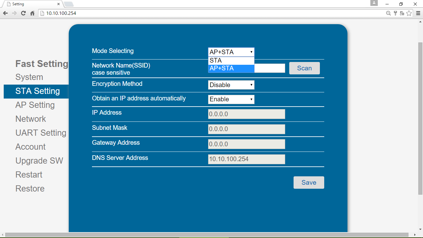
4.In the option of STA Setting,click the scan button to search the wireless you want to connect.In this example,I want to connect to DFRobot WIFI. Then input the wireless password.

5.In the option of Other Setting,you should revise the network parameters setting as the following picture.
Baud Rate :115200bps
Protocol :TCP-Server
Port ID :8899
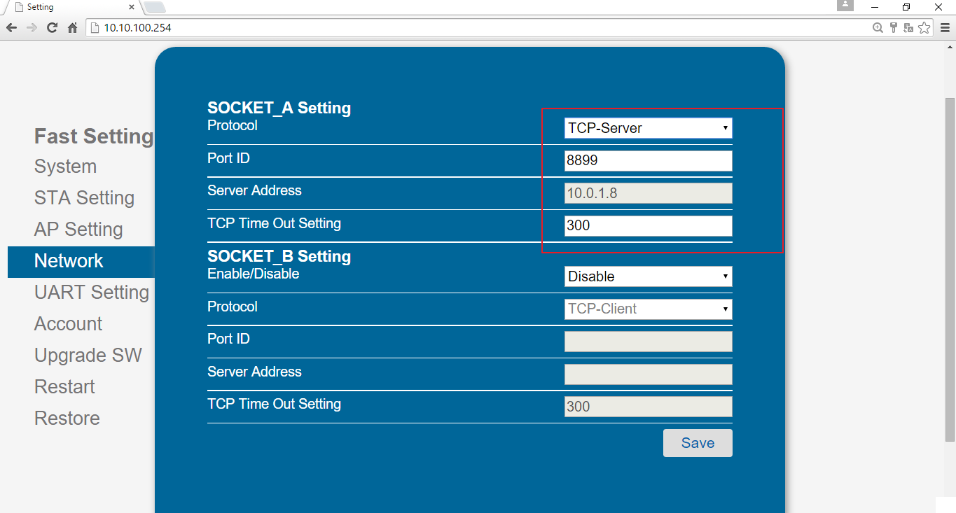
6.After all the settings saved, restart the WIFI shield.

7.Connect the wireless network DFROBOT_WIFI_SHIELD_V3.After that,you can view the IP address of the WIFI shield and other parameters in the option of system.As the following picuure, the IP adress is 192.168.43.141.Remeber this IP address and we will use it soon.
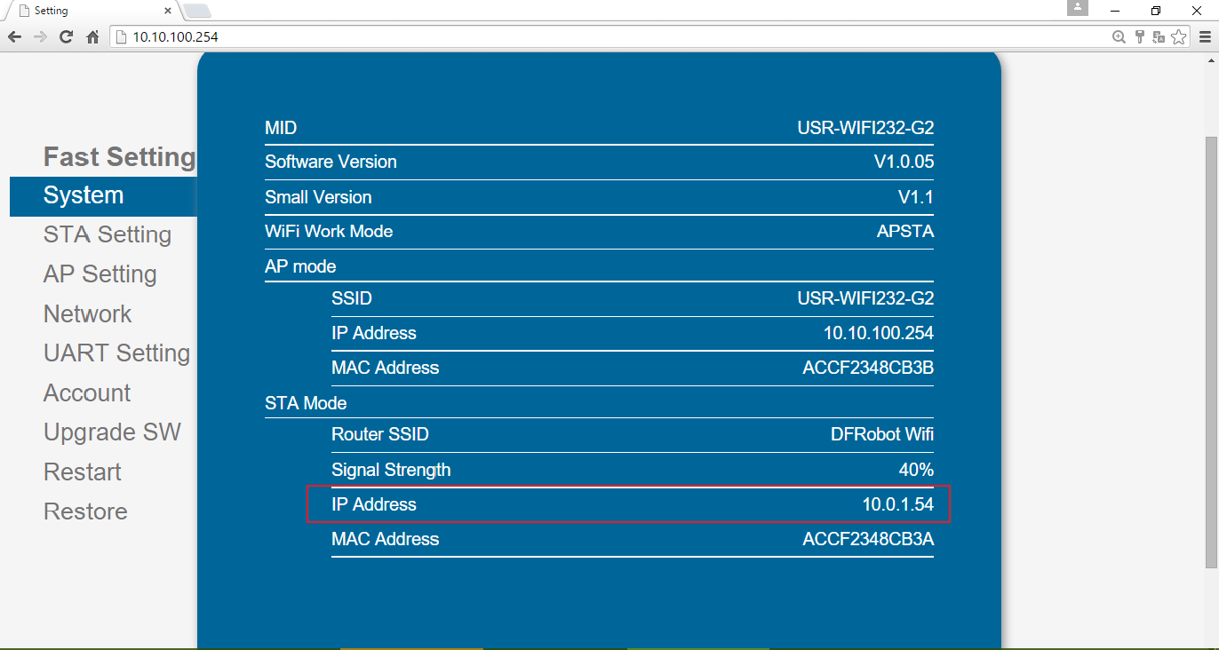
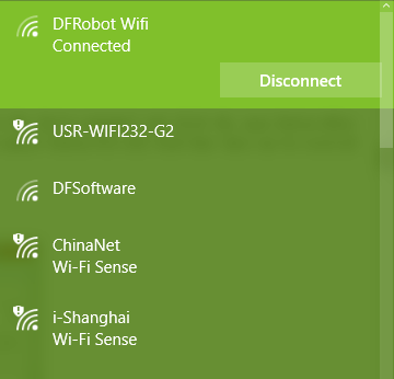
8.Let your computer connect to the wirelss network which has connnected by the WIFI shiled.In this example,I connect to DFRobot WIFI.
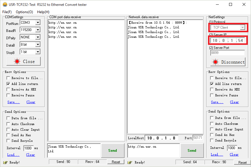
9.Open the software USR-TCP232-Test RS232 to Ethernet Convert tester.Choose the PortNum of the arduino COM(you can look up the portnum in the device manager) and click the open button.After that,you should revise the NetSettings.The protocol is TCP Client ,the server IP is 10.0.1.54 we have just remebered,and the Local host port is the PORT ID we just set.That is 8899.Click the connect button.You will find that data can be received and sended between UART and network port.
AP Mode
1.Put this WIFI shield on the Arduino board and connect to your computer with USB cable.Upload the sample code to the Arduino.When programming,the switch should be turned to PROGRAMME.When done,it should be turned to ARDUINO.
2.Search for wireless network in the computer,and then you should see the network whose name is DFROBOT_WIFI_SHIELD_V3. Connect to it and log in it.

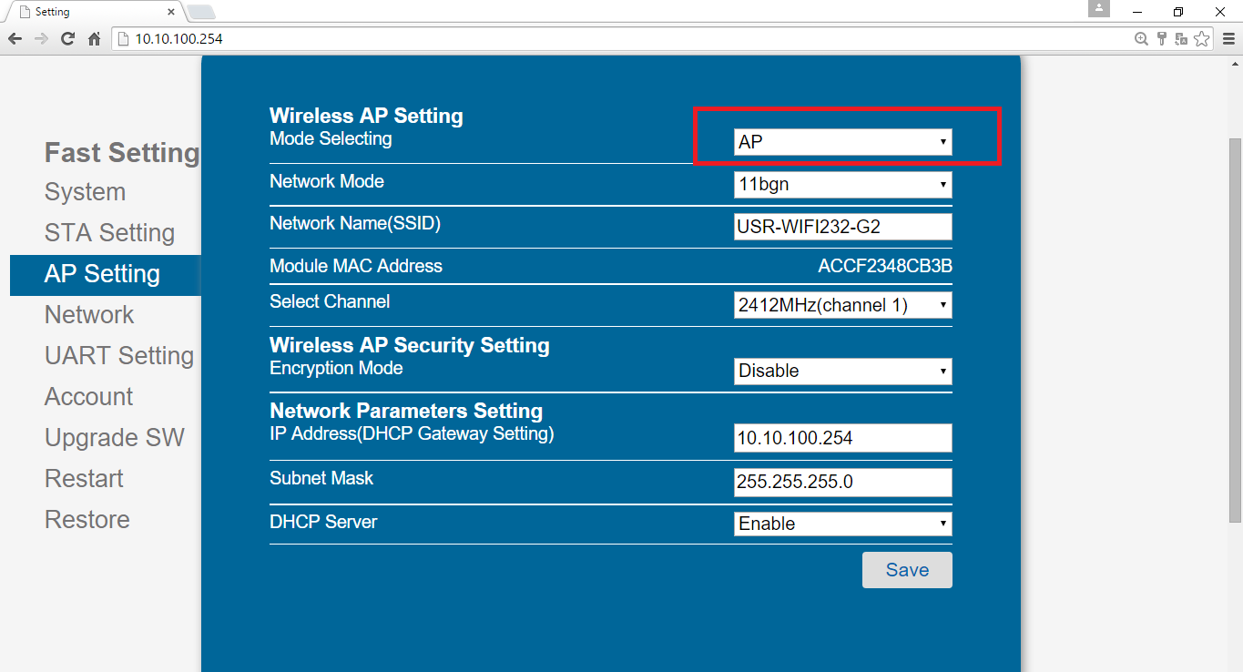
3.In the option of Work Mode,please select the mode: AP mode.In the option of AP Setting,revise the parameters according to the picture given below.
5.In the option of Other Setting,you should revise the network parameters setting.
Baud Rate :115200bps
Protocol :TCP-Server
Port ID :8899

6.After all the settings saved, restart the WIFI shield.

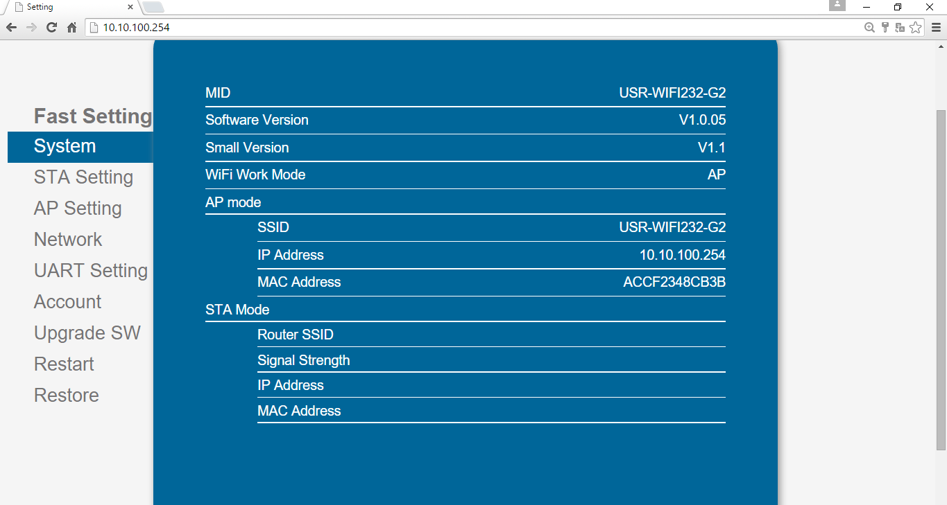
7.Connect the wireless network DFROBOT_WIFI_SHIELD_V3.After that,you can view some parameters.
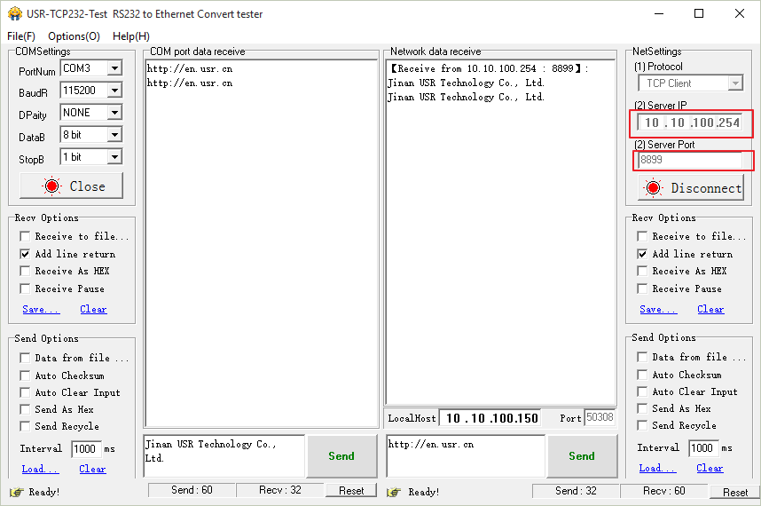
8.Open the software USR-TCP232-Test RS232 to Ethernet Convert tester.You should revise the NetSettings.The protocol is TCP Client ,the server IP is 10.10.100.254,and the Local host port is the PORT ID 8899.Click the connect button.You will find that data can be received and sended between Arduino and network port.
Sample Code
Library installation
This sample code just test the Sleep mode.
#define Sleep_RQ  11  //sleep control input pin of the WIFI shield
#define Sleep_ON  12  //sleep state output pin of the WIFI shield
unsigned char flag;  //Sleep state

void setup()
{
  Serial.begin(115200);    //Baudrate
  pinMode(Sleep_ON,INPUT);
  pinMode(Sleep_RQ,OUTPUT);
  digitalWrite(Sleep_RQ,HIGH);  //Running
  delay(100);

  Serial.println("Start!");         //Test start
  for(unsigned char i = 0;i<10;i++)  //output the state of the shield lasts 20 seconds
  {
    flag = digitalRead(Sleep_ON);
    if(0 == flag)
      Serial.println("D12=0 Sleep");
    else
      Serial.println("D12=1 Active");
    delay(1000);
  }

  Serial.println("Sleep after five second!");    //Sleep after five second
  digitalWrite(Sleep_RQ,LOW);                     //set the shield to sleep mode
  delay(5000);
  digitalWrite(Sleep_RQ,HIGH);
  delay(100);
  Serial.println("Sleep Now!");

  for(unsigned char i = 0;i<10;i++)      //output the state of the shield lasts 20 seconds
  {
    flag = digitalRead(Sleep_ON);
    if(0 == flag)
      Serial.println("D12=0 Sleep");
    else
      Serial.println("D12=1 Active");
    delay(1000);
  }

  Serial.println("Weak up  Now!");
  digitalWrite(Sleep_RQ,LOW);         //set the shield to normal working state
  delay(2000);
  digitalWrite(Sleep_RQ,HIGH);
  delay(100);

  for(unsigned char i = 0;i<10;i++)   //output the state of the shield lasts 20 seconds
  {
    flag = digitalRead(12);
    if(0 == flag)
      Serial.println("D12=0 Sleep");
    else
      Serial.println("D12=1 Active");
    delay(1000);
  }
  Serial.println("Test RX and TX!");
}

void loop()
{
  if(Serial.available()>0)     //Print what serial received.
  {
    char inbyte=Serial.read();
    Serial.print(inbyte);
  }
}
FAQ
For any questions, advice or cool ideas to share, please visit the DFRobot Forum.