Introduction
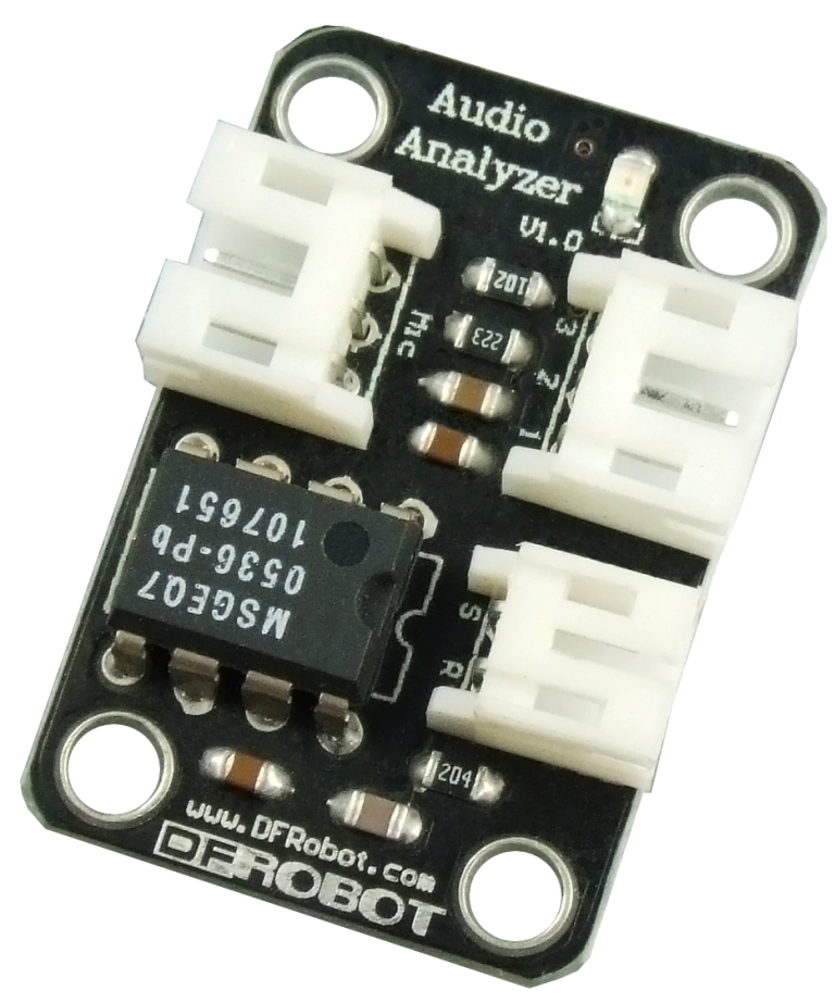
This module features the MSGEQ7 graphic equalizer display filter.It will give your arduino ears. Sound is broken down into seven frequency bands and the peak level for each band can be read. The seven frequencies measured are as follows: 63Hz, 160Hz, 400Hz, 1kHz, 2.5kHz, 6.25kHz and 16kHz.
This module can be used to create sound visualizers, detect patterns in music or add sound activation to your microcontroller.
Technical Specifications
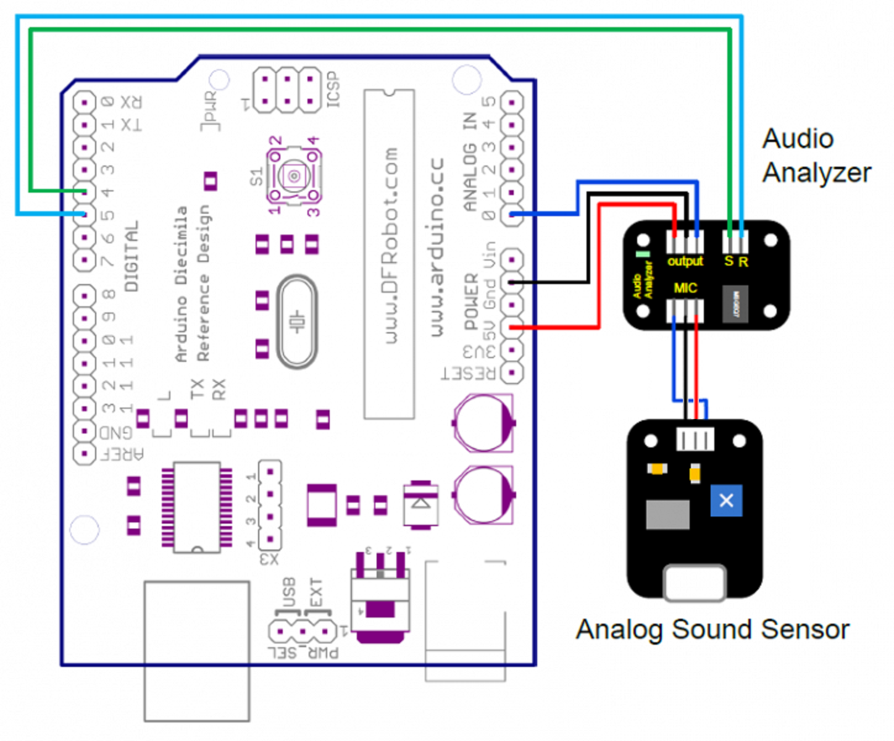
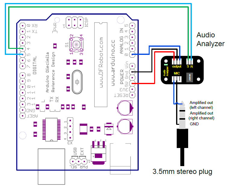
Connection Diagram


Sample code
Arduino IDE Sample code
#include <AudioAnalyzer.h>
//Version 1.2 for Spectrum analyzer


Analyzer Audio = Analyzer(4,5,0);//Strobe pin ->4  RST pin ->5 Analog Pin ->0
//Analyzer Audio = Analyzer();//Strobe->4 RST->5 Analog->5

int FreqVal[7];//

void setup()
{
  Serial.begin(57600);  //Init the baudrate
  Audio.Init();//Init module
}

void loop()
{
  Audio.ReadFreq(FreqVal);//return 7 value of 7 bands pass filiter
                          //Frequency(Hz):63  160  400  1K  2.5K  6.25K  16K
                          //FreqVal[]:      0    1    2    3    4    5    6
  for(int i=0;i<7;i  )
  {
    Serial.print(max((FreqVal[i]-100),0));//Transimit the DC value of the seven bands
    if(i<6)  Serial.print(",");
    else Serial.println();
  }
  delay(20);
}
CVAVR Code:
using atmega128 (clock 16Mhz), usart0 (9600 baud rate), timer1 (scale clock 1024), adc. formula timer1 when use clock freq 16Mhz
Ttimer1 = Periode Timer1
TCNT1 = Register Timer1
N = Scale clock (1, 8, 64, 256 dan 1024)
Tosc = Periode clock
Fosc = Frekuensi clock cristal
Tosc = 1/Fosc
Tosc = 1/16Mhz = 0,0000000625
Ttimer1 = Tosc * (65536 - TCNT1) * N
1 (second) = 0,0000000625 * (65536 - TCNT1) * 1024
TCNT1 = 49911
TCNT1 = C2F7 (in hex) <-- this use in //Timer 1 overflow interrupt service routine
Clock value = Fosc/N
Clock value = 16Mhz/1024 = 15,625 kHz <-- this use in clock value timer1
Can use timer0 or other timer with each formula
/*****************************************************
Chip type           : ATmega128
Program type        : Application
Clock frequency     : 16,000000 MHz
Memory model        : Small
External SRAM size  : 0
Data Stack size     : 1024
*****************************************************/

int sec, band, freq[7], i;
unsigned long int time_a, time_b;
int stat = 0;

#include <mega128.h>
#include <stdio.h>
#include <delay.h>

// Timer 1 overflow interrupt service routine
interrupt [TIM1_OVF] void timer1_ovf_isr(void)
{
// Reinitialize Timer 1 value
TCNT1H=0xC2F7 >> 8;
TCNT1L=0xC2F7 & 0xff;
// Place your code here
sec  ;

}

#define ADC_VREF_TYPE 0x40

// Read the AD conversion result
unsigned int read_adc(unsigned char adc_input)
{

ADMUX=adc_input | (ADC_VREF_TYPE & 0xff);
// Delay needed for the stabilization of the ADC input voltage
delay_us(10);
// Start the AD conversion
ADCSRA|=0x40;
// Wait for the AD conversion to complete
while ((ADCSRA & 0x10)==0);
ADCSRA|=0x10;
return ADCW;

}

void RstModule()
{

PORTD.0 = 0; //S Low
PORTD.1 = 1; //R High
PORTD.0 = 1; //S High
PORTD.0 = 0; //S Low
PORTD.1 = 0; //R Low
delay_us(72);

}

void Init()
{

DDRD.0 = 1; //S pin
DDRD.1 = 1; //R pin
RstModule();

}

void ReadFreq(int *value)
{

if (stat == 0) {
   time_a = sec;
   stat = 1;
} else if (stat == 1) {
   time_b = sec;
   if (time_b - time_a > 3) {
      RstModule();
      stat = 0;
   }
}
for (band=0;band<7;band  ) {
   delay_us(10);
   value[band] = read_adc(0);
   delay_us(50);
   PORTD.0 = 1; //S High
   delay_us(18);
   PORTD.0 = 0; //S Low
}

}

void main(void)
{

// Timer/Counter 1 initialization
// Clock source: System Clock
// Clock value: 15,625 kHz
// Mode: Normal top=FFFFh
// OC1A output: Discon.
// OC1B output: Discon.
// OC1C output: Discon.
// Noise Canceler: Off
// Input Capture on Falling Edge
// Timer 1 Overflow Interrupt: On
// Input Capture Interrupt: Off
// Compare A Match Interrupt: Off
// Compare B Match Interrupt: Off
// Compare C Match Interrupt: Off
TCCR1A=0x00;
TCCR1B=0x05;
TCNT1H=0xC2;
TCNT1L=0xF7;
ICR1H=0x00;
ICR1L=0x00;
OCR1AH=0x00;
OCR1AL=0x00;
OCR1BH=0x00;
OCR1BL=0x00;
OCR1CH=0x00;
OCR1CL=0x00;

// Timer(s)/Counter(s) Interrupt(s) initialization
TIMSK=0x04;
ETIMSK=0x00;

// USART0 initialization
// Communication Parameters: 8 Data, 1 Stop, No Parity
// USART0 Receiver: Off
// USART0 Transmitter: On
// USART0 Mode: Asynchronous
// USART0 Baud Rate: 9600
UCSR0A=0x00;
UCSR0B=0x08;
UCSR0C=0x06;
UBRR0H=0x00;
UBRR0L=0x67;

// Analog Comparator initialization
// Analog Comparator: Off
// Analog Comparator Input Capture by Timer/Counter 1: Off
ACSR=0x80;
SFIOR=0x00;

// ADC initialization
// ADC Clock frequency: 1000,000 kHz
// ADC Voltage Reference: AREF pin
ADMUX=ADC_VREF_TYPE & 0xff;
ADCSRA=0x84;

// Global enable interrupts
#asm("sei")

Init();

while (1)
      {
        ReadFreq(freq);

        for (i=0;i<7;i  ) {
           printf("%d",freq[i]-100);
           if(i<6) printf(", ");
           else printf("\r\n");
        }

        delay_ms(20);

      };
}
NOTE: This code contributed by forum member Pandora.
<br><br><br>
